Positioning device for cross rail in processing machine

A positioning device and processing equipment technology, applied in metal processing equipment, precision positioning equipment, metal processing machinery parts, etc., can solve the problems of increasing the diameter of the piston rod of the cylinder, the diameter of the cylinder cannot be too large, and the non-hydraulicization cannot be realized. Achieve rapid movement control, improve support strength, and improve positioning accuracy

Inactive Publication Date: 2008-08-06
OM MFG CO LTD
View PDF6 Cites 0 Cited by
  • Summary
  • Abstract
  • Description
  • Claims
  • Application Information

AI Technical Summary

Problems solved by technology

[0006] But, because on this horizontal rail, except self-weight, also be provided with the tool rest that is provided with processing tool, therefore in most cases, above-mentioned horizontal rail has considerable weight, owing to utilize cylinder device itself to directly locate and support the Therefore, the diameter of the piston rod of the cylinder has to be increased due to the weight of the horizontal rail. In addition, due to the balance of space, the diameter of the cylinder cannot be too large, so that the pressure area cannot be increased. In this way, the locking of the positioning device To release the driving device, a hydraulic cylinder device capable of outputting a large driving force must be used
[0007] Therefore, in the processing equipment with a large weight of the cross rail, since the hydraulic cylinder device must be used, no hydraulic pressure can be realized, and energy saving and resource saving cannot be realized.

Method used


Image

  • Positioning device for cross rail in processing machine
  • Positioning device for cross rail in processing machine
  • Positioning device for cross rail in processing machine

Examples


Embodiment Construction

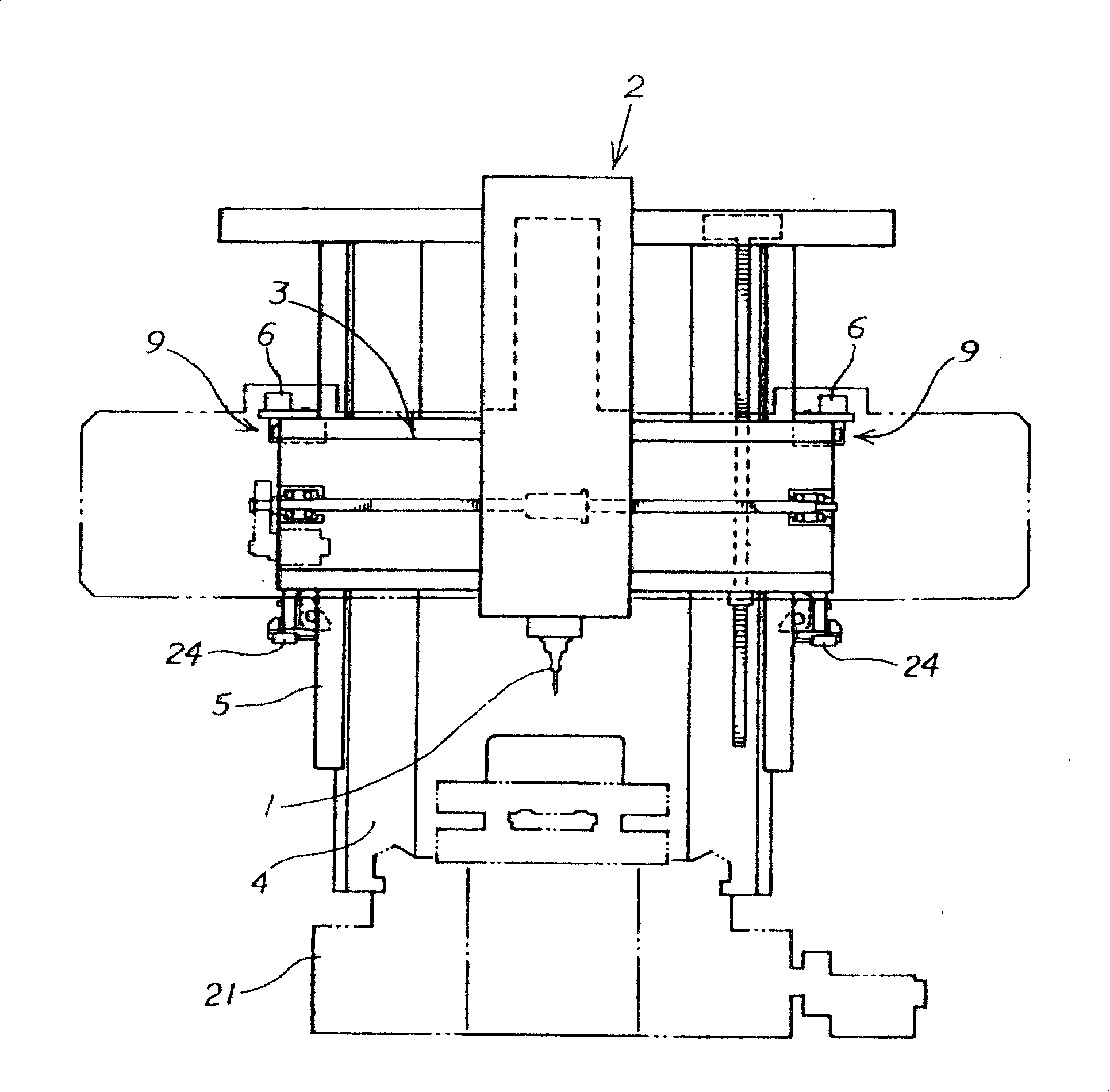
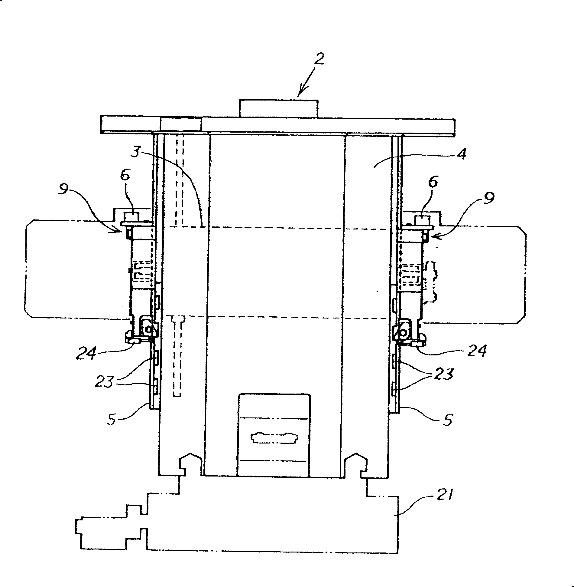
[0030] The following is a brief description of what is considered to be the best embodiment of the present invention (how to implement it) based on the accompanying drawings, and shows its function and effect.

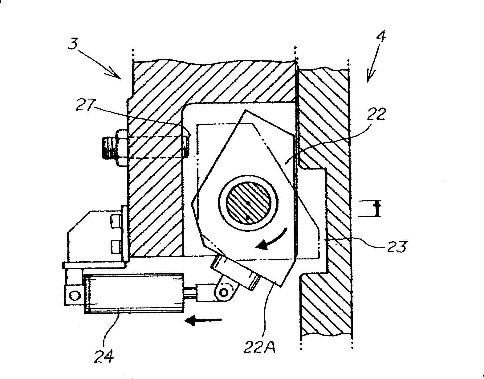
[0031] After the horizontal rail 3 is moved along the guide rail 5, when the above-mentioned rotation locking part 22 is rotated by the driving of the locking release driving device 24, or by the force released by the locking releasing driving device 24, relative to the set The rotation locking part 22 that is in a non-moving state through a plurality of engaging parts 23 is in a protruding state by this rotation, and the protruding part 22A of the rotation locking part 22 selectively engages with one of the plurality of engaging parts 23. The rail 3 is supported and held at a desired position through the engagement (locking).

[0032] In addition, for example, the guide rail 5 is pressed by a clamping device, the cross rail 3 is pulled close to the guide rail 5 and pr...


PUM


Abstract

A positioning device for a cross rail in a processing machine realizes a hydraulic-less environment. The positioning device is capable of sufficiently bearing large load even when an air cylinder device that cannot produce drive force capable of directly opposing load from the cross rail is used as the drive source. In the positioning device, an engaging portion (22) is provided at either a cross rail (3) or a guide rail (5), and portions (23) to be engaged with which the engaging portion (22) selectively engages are arranged at the other. A swing engaging portion (22) of which projection portion (22A) engages a portion (23) to be engaged is provided as the engaging portion (22), where the projection portion (22A) is swung and projected by driving by an engaging / disengaging device (24) or by urging force released by the driving. Movement of the cross rail (3) is permitted when the swing engaging portion (22) swings or swings back, causing the projection portion (22A) to be swung and engaged with or disengaged from a portion (23) to be engaged.

Description

technical field [0001] The invention relates to a positioning device for a cross rail of a processing plant. Background technique [0002] A machining facility that performs NC control on a machining tool that is freely replaceable on a tool holder generally has the following structure. [0003] Its structure is as follows: guide rails are erected on the left and right sides of the upright column on the workbench in a way that can move freely in the front and back, and a beam (rail) is erected along the guide rail in a way to move freely up and down. A tool rest is provided so as to freely move left and right, and predetermined processing tools are vertically installed on the tool holder in a freely replaceable manner, and the movement of the processing tools is controlled by performing NC control on each moving drive device. [0004] The horizontal rail is configured in such a way that both ends of the horizontal rail intersect with the left and right guide rails. The joi...

Claims


Application Information

Patent Timeline
Patent Type & Authority Patents(China)
IPC IPC(8): B23Q16/04B23Q1/58B23Q1/00B23Q1/28B23Q16/00
CPCB23Q1/28B23Q16/001
Inventor 中村多喜夫松本义明清水达雄若月博秋田直人
Owner OM MFG CO LTD
Why Eureka
Try Eureka