Limiting device for high-voltage isolating switch three-station operation mechanism
A high-voltage isolation switch, operating mechanism technology, applied to the power device, contact operating mechanism, electric switch and other directions inside the switch, can solve the problem of not long service life, and achieve extended service life, convenient maintenance and replacement, and extended service life. Effect
- Summary
- Abstract
- Description
- Claims
- Application Information
AI Technical Summary
Problems solved by technology
Method used
Image

Examples
Embodiment Construction
[0025] Below in conjunction with accompanying drawing the implementation details of the present invention are described as follows:
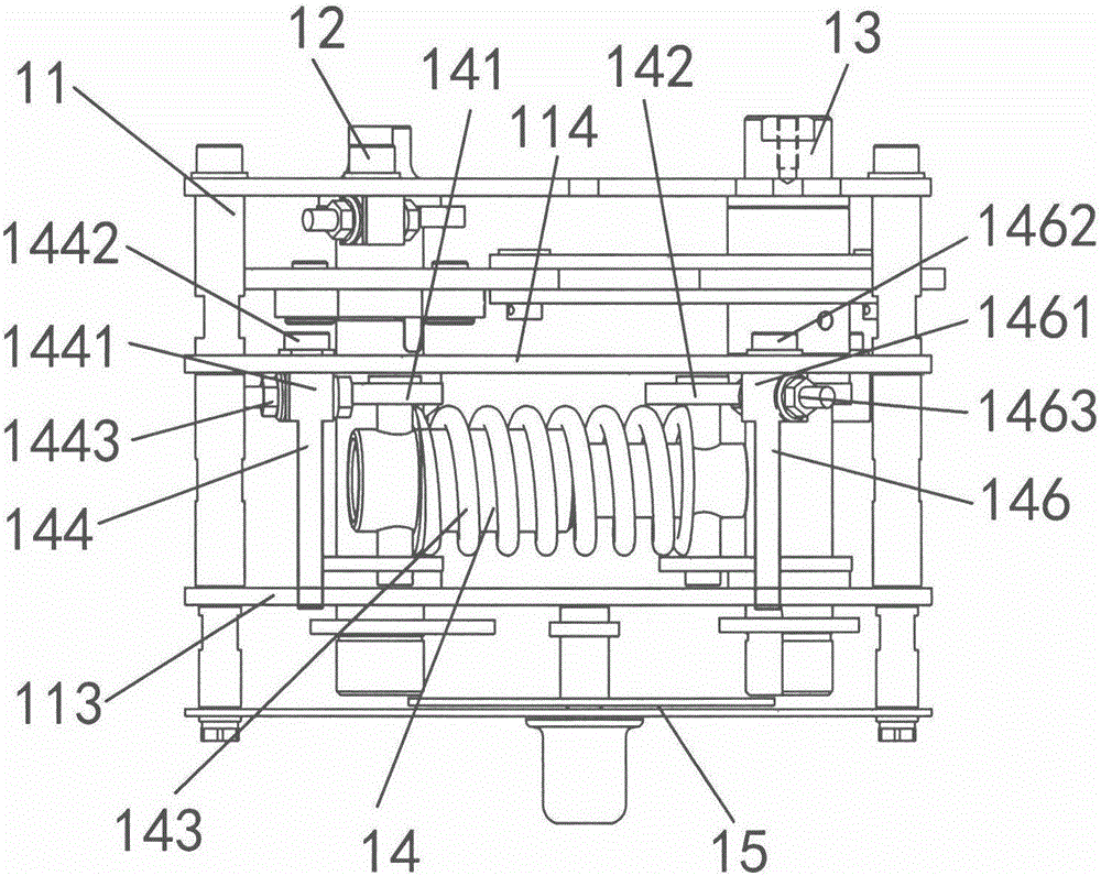
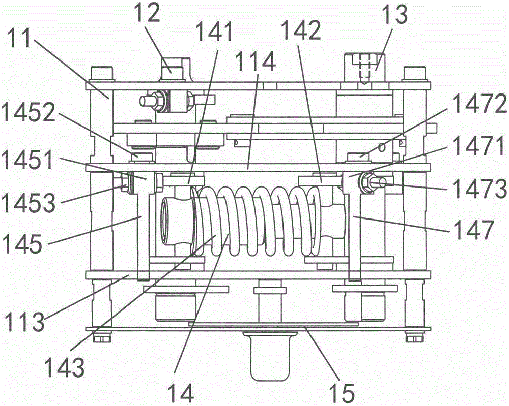
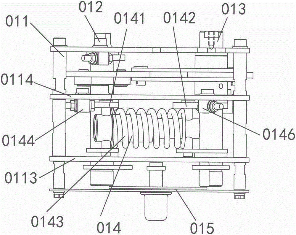
[0026] Such as figure 1 , 2 , 5, and 6, a limit device for a three-position operating mechanism of a high-voltage isolating switch, including a mechanism frame 11, configured on one side of the mechanism frame, passing through the front partition 113, the rear partition 114, and the rear panel configuration The closing and opening operation component 12 is arranged on the other side of the mechanism frame, passing through the front partition 113, the rear partition 114, and the grounding operation component 13 arranged on the rear panel, and is arranged between the front partition 113 and the rear partition 114. The energy storage assembly 14 is a locking assembly 15 arranged between the front panel and the front partition 113, and the energy storage assembly includes a part of the outer periphery fixed on the closing and opening operation sha...
PUM
 Abstract
Description
Claims
Application Information
 - Generate Ideas
- Intellectual Property
- Life Sciences
- Materials
- Tech Scout
- Unparalleled Data Quality
- Higher Quality Content
- 60% Fewer Hallucinations
Browse by: Latest US Patents, China's latest patents, Technical Efficacy Thesaurus, Application Domain, Technology Topic, Popular Technical Reports.
© 2025 PatSnap. All rights reserved.Legal|Privacy policy|Modern Slavery Act Transparency Statement|Sitemap|About US| Contact US: help@patsnap.com