Automatic put and automatic recovery control system

A self-switching, self-recovery, control system technology, applied in emergency power supply arrangements, electrical components, circuit devices, etc., can solve the problems of inability to meet the requirements of power system safety automatic devices, high price, and logic failure.

Active Publication Date: 2015-10-28
昇辉智能科技股份有限公司
View PDF10 Cites 3 Cited by
  • Summary
  • Abstract
  • Description
  • Claims
  • Application Information

AI Technical Summary

Problems solved by technology

[0003] The backup power self-switching device can play a certain role in improving reliability, but there are few on-site backup and self-switching products specifically for low-voltage power distribution systems, and the existing backup power self-switching device can only realize the on-site switching of a single substation The backup power supply is automatically switched on. When the internal wiring or operation mode of the substation changes, the original logic will become invalid, resulting in the failure of the backup power supply, and the automatic input function of the remote backup power supply cannot be realized.
In addition, due to the single implementation method, imperfect functions, low reliability, high price, and the inability to obtain comprehensive information on the power grid, it is difficult to achieve cooperation with safety automatic devices, and it cannot ideally solve the overload situation. The system places ever-increasing demands on safety automation

Method used


Image

  • Automatic put and automatic recovery control system
  • Automatic put and automatic recovery control system
  • Automatic put and automatic recovery control system

Examples


Embodiment 1

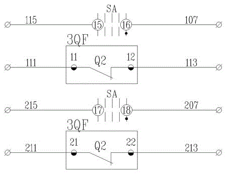
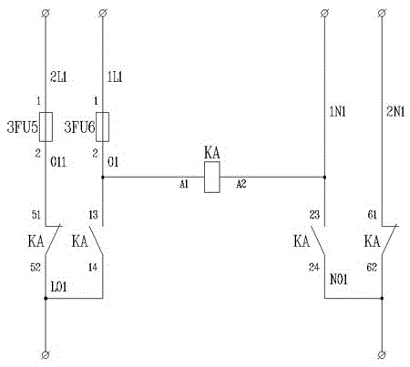
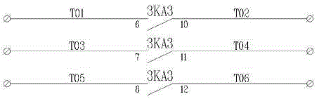
[0064] Embodiment 1, a kind of self-injection and self-recovery control system, refer to figure 1 , figure 2 , image 3 , Figure 4 , 1# incoming line cabinet, bus coupling cabinet, and 2# incoming line cabinet are connected to the background safety automatic device through the bus. The 1# incoming line cabinet is 1# voltage sampling unit, 1# current sampling unit, 1# multiple Function measurement and control module power supply unit, 1# switch state upload unit are respectively connected with 1# multi-function measurement and control module communication unit, 1# multi-function measurement and control module communication unit is connected with 1# circuit breaker control unit, 1# voltage sampling unit is connected with 1# self-injection Self-resetting unit, 1# self-transfer and self-recovery unit is connected to 1# circuit breaker control unit, and the power switching unit of the bus coupler cabinet is respectively connected to 1# self-transfer and self-recovery unit, 1# c...

Embodiment 2

[0068] Embodiment 2, a kind of self-injection self-recovery control system, refer to Figure 1 to Figure 27 , on the basis of Embodiment 1, the 1# multifunctional measurement and control module power supply circuit is that the 1 and 2 ends of the multifunctional measurement and control module 1PD are respectively connected to the live wire and the neutral wire of the alternating current;

[0069] The 1# current sampling unit is the 5, 7, 9 terminals of the multifunctional measurement and control module 1PD, the S2 terminals of the current transformers 1TAa, 1TAb, 1Tac are short-circuited and grounded, and the 4, 6 and 8 terminals of the multifunctional measurement and control module 1PD Connect to S1 terminal of current transformer 1TAa, 1TAb, 1Tac respectively;

[0070] The 1# switch status uploading unit is that terminal 71 of the multi-functional measurement and control module 1PD is connected to terminal 5 of the intermediate relay 1KA5, terminal 72 is connected to termina...


PUM


Abstract

The invention discloses an automatic put and automatic recovery control system. A No.1 wire inlet cabinet, a bus coupler cabinet and a No.2 wire inlet cabinet are connected with a background safety automatic device through buses. Wire inlet voltage signals of the No.1 wire inlet cabinet and the No.2 wire inlet cabinet are connected through a voltage sampling unit, a wire inlet breaker at a fault side is disconnected automatically when No.1 wire inlet or No.2 wire inlet is out of order, the bus coupler cabinet is input, when a wire input power supply recovers, the bus coupler cabinet is disconnected automatically, the wire inlet breaker is put, Through respective multifunctional measurement and control modules, collected power grid information of current signals, voltage signals of the No.1 wire inlet cabinet, the bus coupler cabinet and theNo.2 wire inlet cabinet, the switch state of the breaker and the like is uploaded to the background safety automatic device by utilization of the communication unit of the multifunctional measurement and control module through buses, and a control connection and disconnection instruction sent back from the background safety automatic device is received. Switching of a plurality of functional modes of automatic put and automatic recovery, automatic put and no automatic recovery, , and manual control and remote control of a switch cabinet and the like is achieved through a change over switch arranged at the bus coupler cabinet.

Description

technical field [0001] The invention belongs to the technical field of power supply equipment, and in particular relates to a self-input and self-recovery control system. Background technique [0002] With the development of social economy, the demand for electric power is increasing, the structure of power grid is becoming more and more complex, and the reliability of power supply is required to be higher and higher. When the whole system breaks down, dispatchers or operating personnel can only rely on the manual input of backup power, which greatly reduces the operating efficiency and power supply reliability of the power grid. It is an economical and effective technical measure to provide users with uninterrupted power supply by using the backup power self-injection device, and it has been widely used in modern power supply systems. [0003] The backup power self-switching device can play a certain role in improving reliability, but there are few on-site backup and self-...

Claims


Application Information

Patent Timeline
Patent Type & Authority Applications(China)
IPC IPC(8): H02J9/06
Inventor 孙洪峰董志浩姜坤张小妮郭鹏蛟迟万旭
Owner 昇辉智能科技股份有限公司
Why Eureka
Try Eureka