A speed measurement method of permanent magnet synchronous motor based on resolver

A permanent magnet synchronous motor and rotary transformer technology, applied in the control of generators, motor generators, AC motors, etc., can solve the problems of poor control performance and low measurement accuracy, and achieve high speed measurement accuracy and simple measurement methods , the effect of expanding occasions and scope

Active Publication Date: 2018-02-09
BEIJING INST OF CONTROL ENG
View PDF4 Cites 0 Cited by
  • Summary
  • Abstract
  • Description
  • Claims
  • Application Information

AI Technical Summary

Problems solved by technology

[0014] The technical problem to be solved by the present invention is: a high-precision speed measurement method for the permanent magnet synchronous motor driven by the rotary transformer at low speed is proposed, which can significantly improve the speed measurement accuracy of the permanent magnet synchronous motor driven by the low speed, and improve the drive control performance. And the implementation method is simple, does not need to add additional hardware, and the cost is low; it overcomes the problem of low measurement accuracy and poor control performance of the traditional resolver speed measurement method in the case of permanent magnet synchronous motor driving at low speed

Method used


Image

  • A speed measurement method of permanent magnet synchronous motor based on resolver
  • A speed measurement method of permanent magnet synchronous motor based on resolver
  • A speed measurement method of permanent magnet synchronous motor based on resolver

Examples


Embodiment Construction

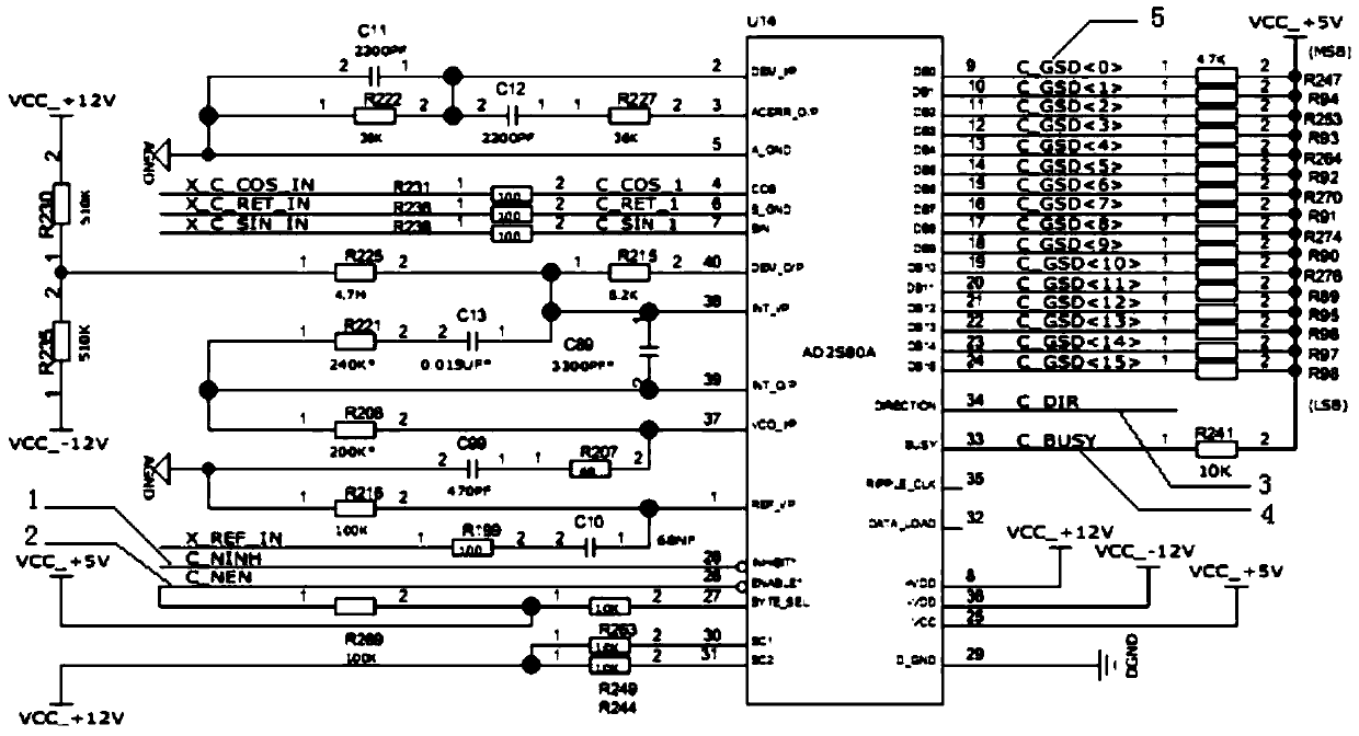
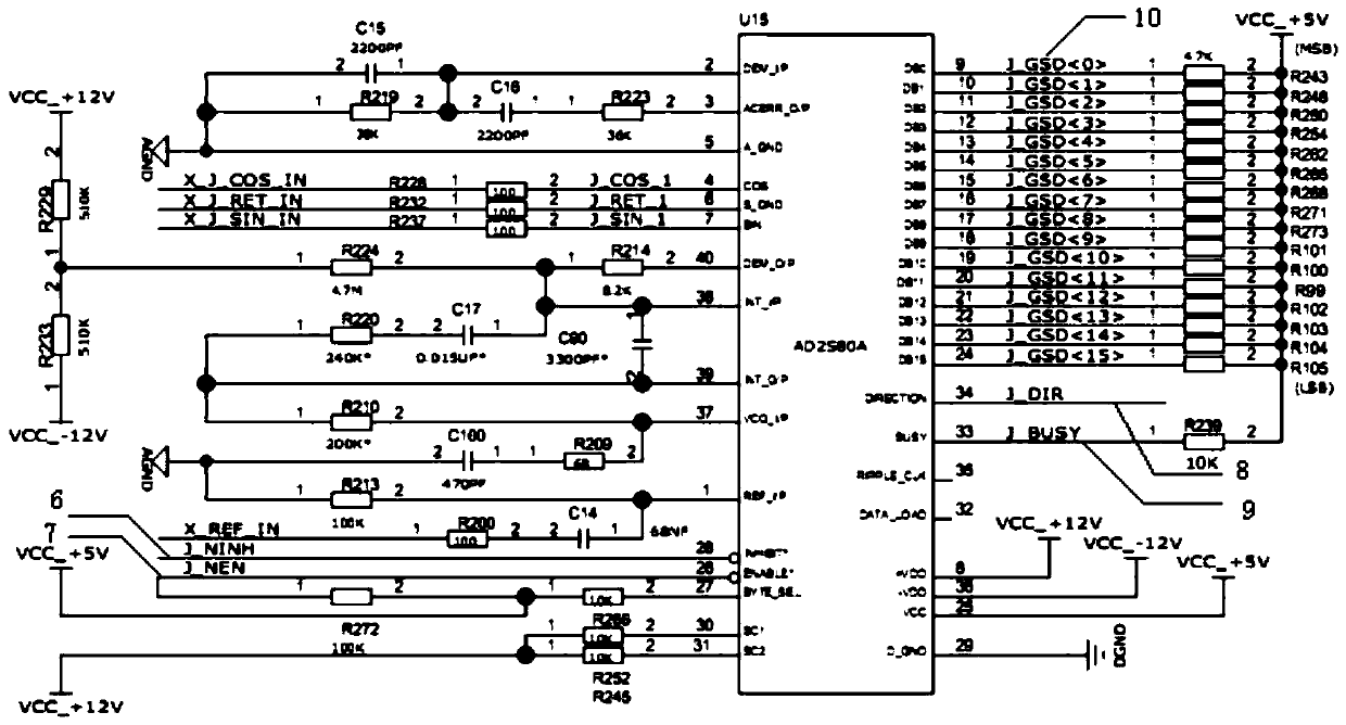
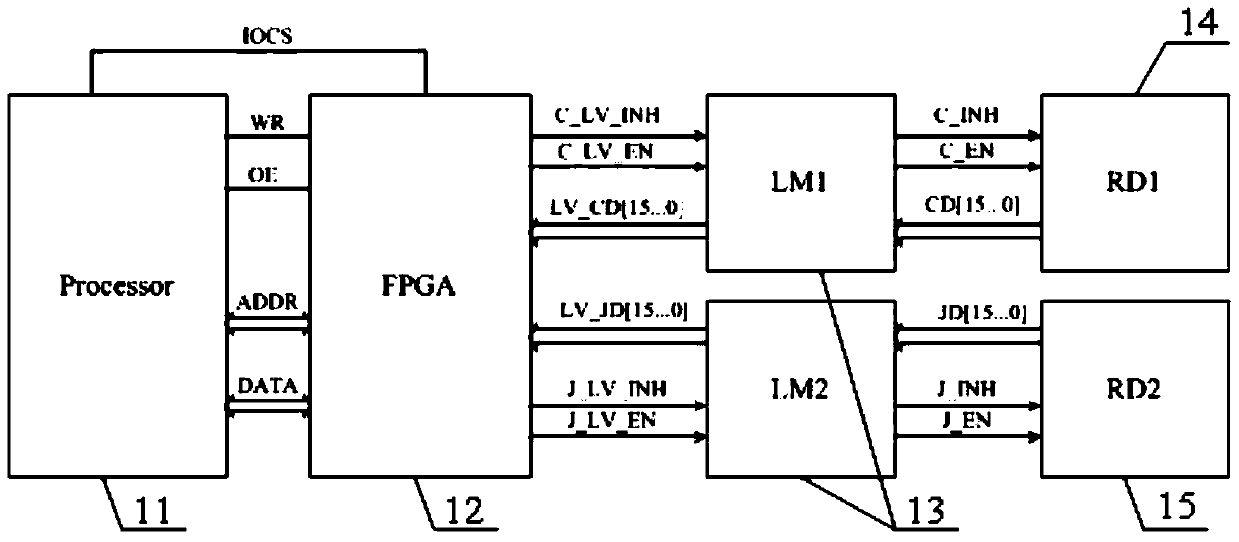
[0032] A high-precision speed measurement method for the permanent magnet synchronous low-speed drive of the resolver, using 1 pair of ultra-rough machine and 32 pairs of extremely fine machine resolvers to collect the angle of the motor, the peripheral circuit design see figure 1 shown and figure 2 As shown, the sine and cosine signals of the resolvers of the rough machine and the fine machine are connected to the corresponding pins of the demodulation circuit chip, the decoder enable signal EN, the data conversion prohibition signal INH, and the bus data bits are respectively connected to the FPGA, and through the peripheral circuit The design of resistors and capacitors can set the working bandwidth and maximum tracking rate of the decoding circuit. In this embodiment, the working bandwidth of the rough-finishing machine demodulation chip is 178Hz, and the maximum tracking rate is 4.82rps. The present invention requires that the resolver decoder is always in the data conve...


PUM


Abstract

The present invention provides a method for measuring the speed of a permanent magnet synchronous motor based on a rotary transformer, comprising: S1, using the rotary transformer to collect the angle of the motor; S2, FPGA reads the bus data of the rotary transformer decoder, and uses the bus data bit signal The change of the speed measurement pulse is generated, the time interval between two speed measurement pulses is measured, and the time interval is sent to the processor; S3, the processor uses the data of the time interval to calculate the speed measurement result. The method of the invention adopts FPGA to realize the generation of speed measurement interval pulses and realizes the timer counting between interval pulses, and the processor receives the timer count of FPGA and performs calculation to realize the speed measurement under low-speed driving. The method of the invention is simple to implement, has high speed measurement accuracy, and can easily realize the high-performance control of the low-speed drive of the permanent magnet synchronous motor under the speed measurement mode of the rotary transformer, and improves the dynamic and steady-state control performance of the permanent magnet synchronous motor under the low-speed drive.

Description

technical field [0001] The invention relates to the field of permanent magnet synchronous motors, in particular to a method for measuring the speed of permanent magnet synchronous motors based on a resolver. Background technique [0002] Permanent magnet synchronous motor drives are widely used due to their advantages such as simple maintenance, high efficiency, and good low-speed performance. The permanent magnet synchronous motor drive control system adopts vector control to achieve field-oriented control. The core is to realize the complete decoupling of the excitation component and torque component of the stator current, that is, to use the coordinate transformation principle to realize the transformation between the stationary coordinate and the rotating coordinate of the stator current. Therefore, the control system must know the angle between the coordinate changes, that is, the position of the motor rotor. [0003] At present, resolvers and analog encoders based on ...

Claims


Application Information

Patent Timeline
Patent Type & Authority Patents(China)
IPC IPC(8): H02P21/18H02P25/022
Inventor 郭超勇张猛熊军田宇斌
Owner BEIJING INST OF CONTROL ENG
Why Eureka
Try Eureka