Improved external ventricular drainage tube

A technology of external drainage tube and drainage tube, which is applied in the direction of wound drainage, catheter, medical science, etc., can solve the problems of drainage fluid leakage, cerebrospinal fluid retrograde infection, and the inability to know the specific position of the side hole area at the head end, etc., so as to avoid The effect of side wall leakage and avoiding retrograde infection

Inactive Publication Date: 2015-11-04
SECOND MILITARY MEDICAL UNIV OF THE PEOPLES LIBERATION ARMY
View PDF15 Cites 4 Cited by
  • Summary
  • Abstract
  • Description
  • Claims
  • Application Information

AI Technical Summary

Problems solved by technology

First, CT and other imaging examinations after the drainage tube is inserted into the ventricle cannot know the specific location of the side hole area at the head end. Doctors can only estimate the location of the side hole based on experience, and the judgment of the drainage effect is poor.
Second, in order to facilitate the insertion of the drainage tube into the patient's ventricle, in addition to the intracranial pressure sensing circuit, a metal support rod is also provided in the drainage tube to facilitate the puncture of the ventricle. Although the side seam of the silicone drainage tube is generally kept closed, when the drainage tube is bent, the drainage fluid is prone to leakage at the tear of the side wall, and bacteria can reversely enter the ventricular system through the leakage, forming Cerebrospinal fluid retrograde infection
[0004] There is no report on an external ventricular drainage device that can simultaneously dynamically monitor intracranial pressure, intuitively observe and control the specific depth of the side hole of the drainage tube by medical personnel, and effectively avoid leakage of the ventricular drainage tube from the skin during the perioperative period.

Method used


Image

  • Improved external ventricular drainage tube
  • Improved external ventricular drainage tube

Examples


Embodiment

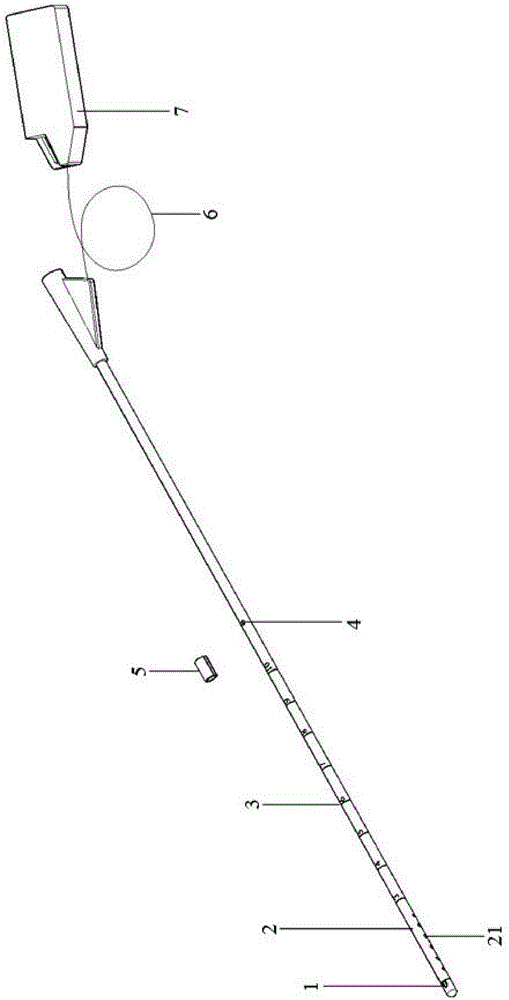
[0025] Please see figure 1 , figure 1 It is a schematic diagram of an improved external ventricular drainage tube of the present invention. The front section of the drainage tube is provided with a pressure sensor 1, a drainage side hole area 2 and a scale 3, and the middle section of the drainage tube is provided with a small hole 4, and the outside of the small hole 4 is wrapped with a movable rubber sleeve 5. A metal support rod (not shown) is built inside, and one end of the metal support rod can pass through the small hole 4, and the end of the drainage tube is provided with a monitoring port 7, and the monitoring port 7 is connected to the monitoring sensor through the monitoring port connection line 6 1 connection, the monitoring port connection line 6 runs on the inner wall of the drainage tube.

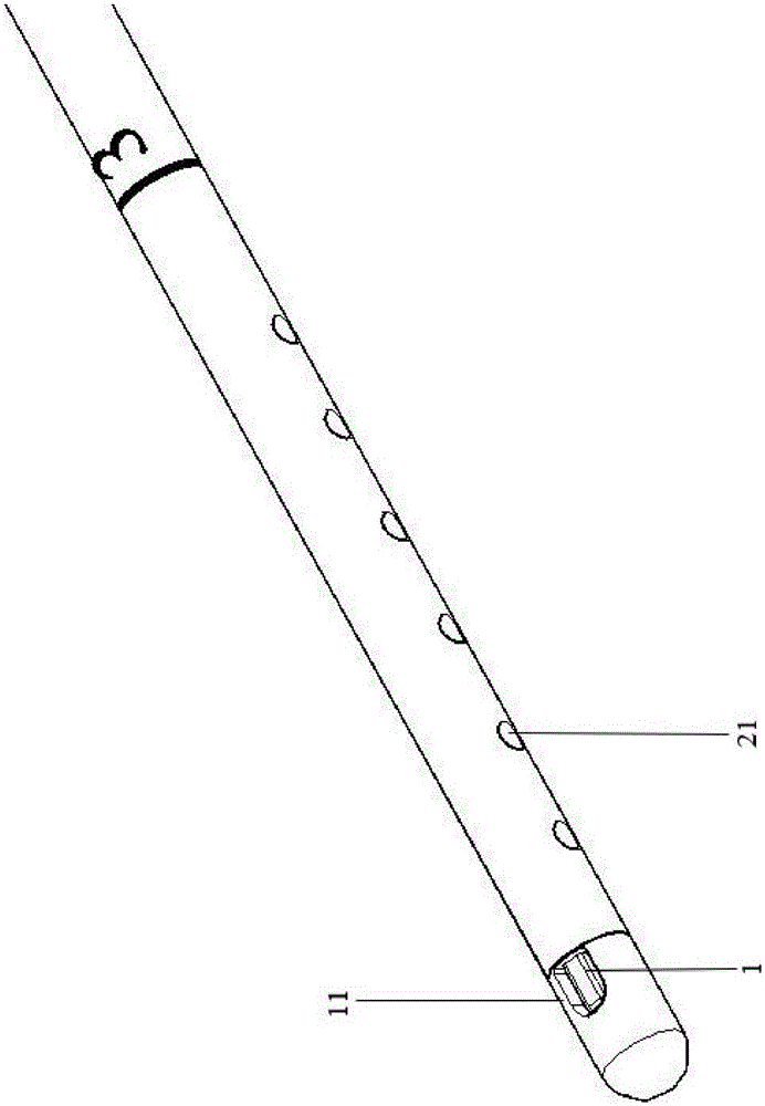
[0026] Please see figure 2 , figure 2 It is a schematic diagram of the structure of the head end of the external ventricular drainage tube. The head end of the drainag...


PUM


Abstract

The invention relates to an improved external ventricular drainage tube. A pressure sensor, a drainage side hole area and scales are arranged at the front section of the external ventricular drainage, wherein a small hole is formed in the middle section of the drainage tube, the outer side of the small hole is coated with a movable rubber sleeve, a metal support rod is arranged in the drainage tube, and a monitoring port is formed in the tail end of the drainage tube and connected with the pressure sensor through a monitoring port connecting line. The drainage tube has the advantages as follows: the pressure sensor is arranged at the front end of the drainage tube and can monitor the intracranial pressure of a patient in real time; a developing material is arranged in the drainage side hole area at the front section of the drainage tube, can develop under CT (computed tomography) and facilitates clinical observation of the specific position of the drainage side hole area and judgment of the drainage effect; by means of the metal support rod in the drainage tube, the outer layer of the drainage tube can be placed in a ventricle conveniently in a puncture manner; the metal support rod can be pulled out of the small hole in the middle section of the drainage tube, and leakage from the side wall of the drainage tube and retrograde infection after pulling out of the support rod can be effectively avoided.

Description

technical field [0001] The invention relates to an external ventricular drainage tube, in particular to an improved external ventricular drainage tube. Background technique [0002] As a key measure to release cerebrospinal fluid and reduce intracranial pressure, external ventricular drainage is currently widely used in neurosurgery and popularized in most grassroots medical units. For hemorrhagic or ischemic cerebrovascular diseases, external ventricular drainage plays an important role in the perioperative period of complex intracranial tumors. At present, it has become a trend to implant intracranial pressure sensor components to dynamically observe intracranial pressure during external ventricular drainage. The intracranial pressure sensor is generally integrated in the ventricular drainage tube for accurate monitoring of the real intracranial pressure deep in the brain. [0003] There are many problems in the use of external ventricular drainage tubes (such as Johnson...

Claims


Application Information

Patent Timeline
Patent Type & Authority Applications(China)
IPC IPC(8): A61M25/00A61M25/095A61B5/03
CPCA61M25/007A61M27/00A61M2025/0002A61M2025/0008
Inventor 戴冬伟鲁琼刘建民
Owner SECOND MILITARY MEDICAL UNIV OF THE PEOPLES LIBERATION ARMY
Why Eureka
Try Eureka