Female die for ceramic cup product and using method thereof

A technology for ceramic cups and products, which is applied to ceramic molding machines, ceramic molding cores, ceramic molding mandrels, etc., can solve the problems of blurred patterns, poor fluidity and lack of concave and convex surfaces, and achieve the effect of clear concave and convex patterns.

Active Publication Date: 2015-11-04
广东皓业青花彩瓷股份有限公司
View PDF11 Cites 7 Cited by
  • Summary
  • Abstract
  • Description
  • Claims
  • Application Information

AI Technical Summary

Problems solved by technology

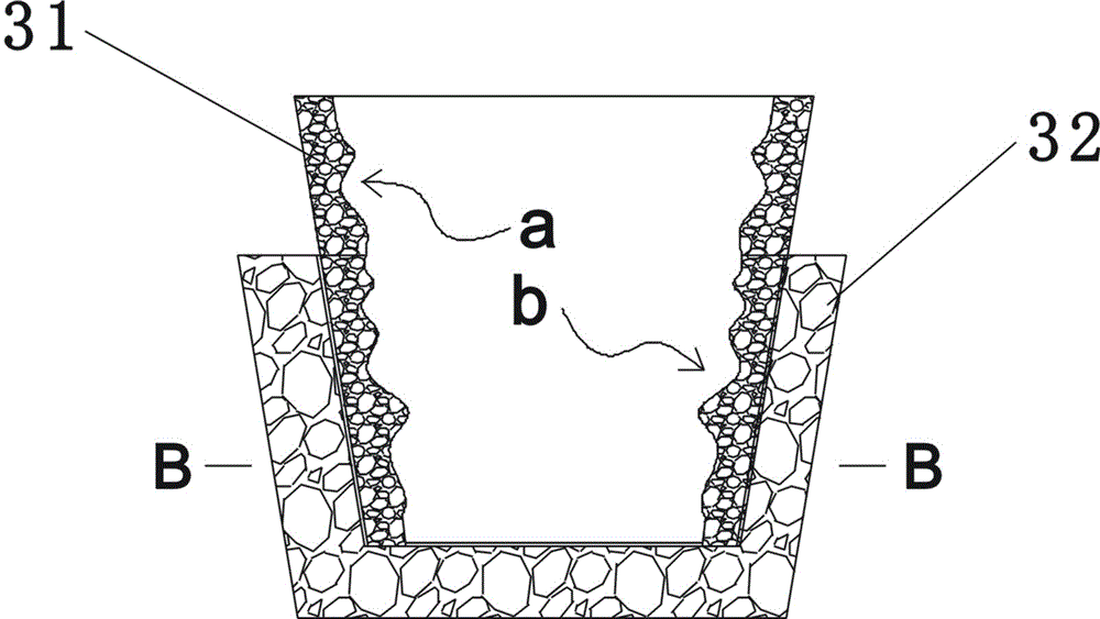
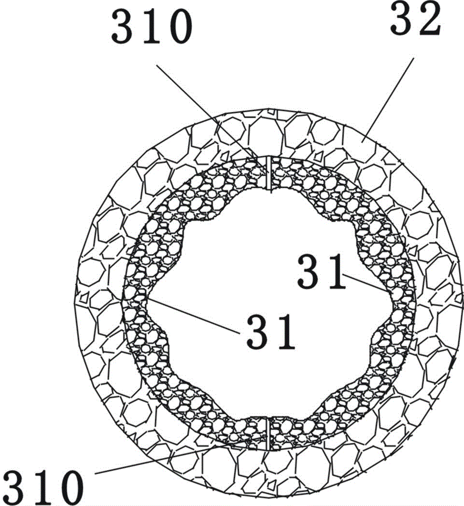
[0005] Due to the above reasons, if the outer peripheral surface of the existing ceramic cup wants to form a concave-convex pattern, the demoulding process is difficult, and the demoulding process will cause wear and tear on the concave-convex pattern, and the mold design is complicated; in addition, because the fluidity of gypsum is inherently poor, And the fluidity on the concave-convex surface is even worse, so in the process of utilizing the cup-shaped mold core 11 to make the gypsum female mold, the gypsum at the concave-convex surface will not be full and compact, for example, in Figure 16 The arrows c and d in the figure point to the inner corner of the cup-shaped mold core 11. It is difficult for the gypsum to squeeze in densely, which will lead to the problems of unclear concave-convex patterns, fuzzy patterns, unsharp lines or partial missing.

Method used


Image

  • Female die for ceramic cup product and using method thereof
  • Female die for ceramic cup product and using method thereof
  • Female die for ceramic cup product and using method thereof

Examples


Embodiment 1

[0040] Figure 5 , Image 6 , Figure 7 The master mold of the shown ceramic cup product includes a first set of master mold assembly 1, and the first set of master mold assembly 1 includes a first mold core 11, a circular first steel mold cover 12, the first mold The core 11 is arranged in the center of the first steel mold cover 12, there is a radial gap between the first mold core 11 and the center of the first steel mold cover 12, the inner peripheral surface of the first steel mold cover 12 is smooth, and the first steel mold cover 12 and the first mold core 11 are formed as a circular first mold cavity 13, the lower bottom surface of the first mold core 11 (such as Figure 5 (shown on the MN surface in the middle) closely contacts the bottom 120 of the first steel formwork 12, leaving no vertical gap between the two; Figure 15 As shown, the first mold core 11 includes a mold core body 110 and a mold core cover 111. The mold core body 110 is made of silica gel. The mo...

Embodiment 2

[0042] A method for using the ceramic cup product master mold described in Embodiment 1, comprising the following steps:

[0043] (1) Under normal pressure, assemble the valve core of the first mold core 1 to the nozzle body of the valve so that the air pressure inside the cavity 113 of the first mold core is normal pressure; The left and right parts of the first mold cavity 13 of a set of master mold components are filled with gypsum respectively;

[0044] (2) After the gypsum pouring is completed, use the inflation device to inflate the cavity of the first mold core through the valve 112, so that the air pressure in the cavity of the first mold core reaches 2.5 standard atmospheric pressure, and the mold core body 110 of the first mold core Expand and squeeze the gypsum in the first mold cavity to make it dense, and then let the gypsum solidify. During the gypsum solidification process, the air pressure in the first mold core cavity remains constant at 2.5 standard atmospher...


PUM

PropertyMeasurementUnit
thicknessaaaaaaaaaa
thicknessaaaaaaaaaa

Abstract

The invention discloses a female die for a ceramic cup product. The female die for the ceramic cup product comprises a first female die assembly. The first female die assembly comprises a first die core and a first annular steel die sleeve. A first annular die cavity is formed between the first steel die sleeve and the first die core. The first die core comprises a die core body and a die core cover. The die core body is made of silica gel. The die core body is hollow, so that a cavity is formed in the die core body. Concave-convex patterns are formed on the outer circumferential surface of the die core body. An inflating valve which can be used for inflation and deflation is further mounted on the die core cover. The female die is further provided with a second female die assembly. The second female die assembly comprises a second die core and a second annular steel die sleeve. A second die cavity is formed by a vertical gap and a radial gap between the second die core and the second steel die sleeve. The invention further provides a using method of the female die for the ceramic cup product. The distinct concave-convex patterns are formed on a ceramic cup finally manufactured; in addition, die releasing can be achieved easily, and abrasion to the concave-convex patterns is avoided in the die releasing process.

Description

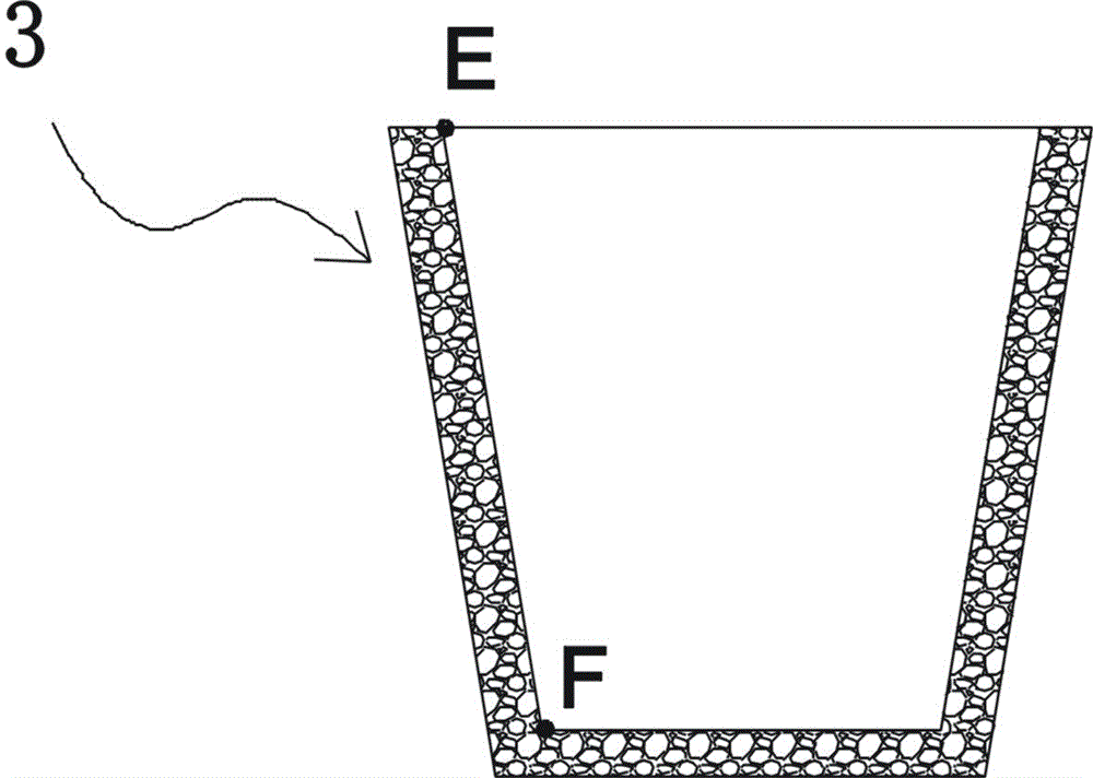
technical field [0001] The invention belongs to the technical field of ceramic production equipment, and in particular relates to a master mold of a ceramic cup product and a use method thereof. Background technique [0002] The green body of the ceramic cup product is generally formed by rolling with a female mold, wherein the inner peripheral surface of the female mold 3 (such as figure 1 The shape of the surface shown in EF is corresponding to the shape of the outer peripheral surface of the ceramic cup product to be made. When forming, the female mold 3 is placed on a constantly rotating turntable, the mud is placed in the female mold 3, the mud is attached to the inner peripheral surface of the female mold, the rolling head 33 is pressed against the inner peripheral surface of the mud, and rolled The indenter 33 and the female mold 3 rotate around their own axes respectively. Due to the rotation of the rolling head, the mud in the female mold is rolled and extended int...

Claims


Application Information

Patent Timeline
Patent Type & Authority Applications(China)
IPC IPC(8): B28B7/44B28B7/32B28B7/28B28B3/12B28B11/00
CPCB28B3/12B28B7/285B28B7/32B28B7/44B28B11/001
Inventor 郑秋荣
Owner 广东皓业青花彩瓷股份有限公司
Why Eureka
Try Eureka