Printing head walking structure of 3D printer

A 3D printer and print head technology, applied in the direction of additive processing, etc., can solve the problems of poor moving stability of working parts, increased use and maintenance costs, complex slider guide rail structure, etc., to achieve stable moving, simple structure, and satisfying The effect of precision requirements

Inactive Publication Date: 2015-11-04
UNIV OF JINAN
View PDF5 Cites 3 Cited by
  • Summary
  • Abstract
  • Description
  • Claims
  • Application Information

AI Technical Summary

Problems solved by technology

[0002] The walking structure of the print head of the 3D printer in the prior art widely uses the synchronous belt and the slider guide rail as the structure for transmitting power, and connects the synchronous belt with the printer head to realize the smooth movement of the working parts. The synchronous belt of the prior art is made of plastic material The closed circular ring structure made is easy to deform due to the plastic material during use, especially under the action of friction and tensile tension during the working process, it is easy to elongate and produce plastic deformation, and it is inconvenient to adjust after deformation. The working parts have poor moving stability and large speed fluctuations, which affect the accuracy of the transmission, thereby affecting the accuracy of the processed workpiece, and even cause unqualified products. After the deformation is out of tolerance, the synchronous belt is scrapped. The structure of the guide rail is also relatively complicated, and it is prone to failure, which increases the cost of use and maintenance

Method used


Image

  • Printing head walking structure of 3D printer
  • Printing head walking structure of 3D printer
  • Printing head walking structure of 3D printer

Examples


Embodiment Construction

[0023] In order to better understand the present invention, the implementation manner of the present invention will be explained in detail below in conjunction with the accompanying drawings.

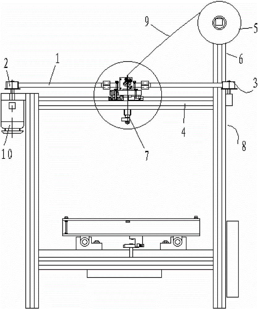
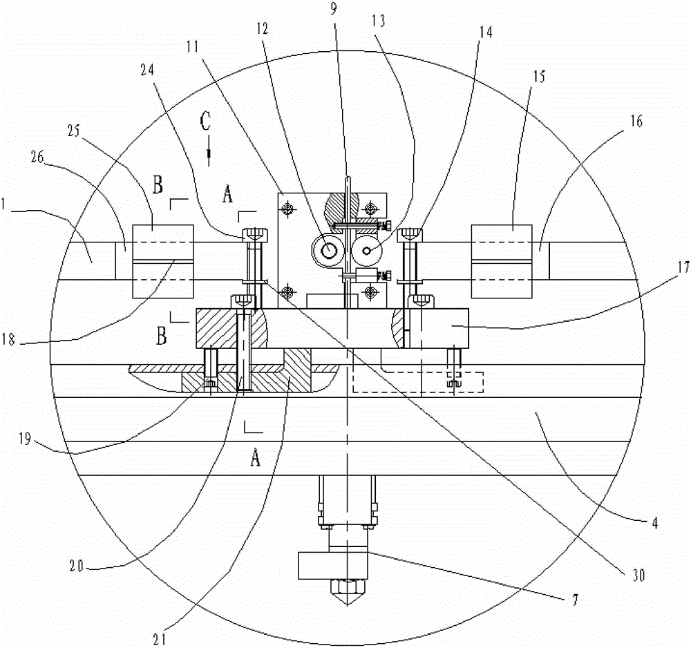
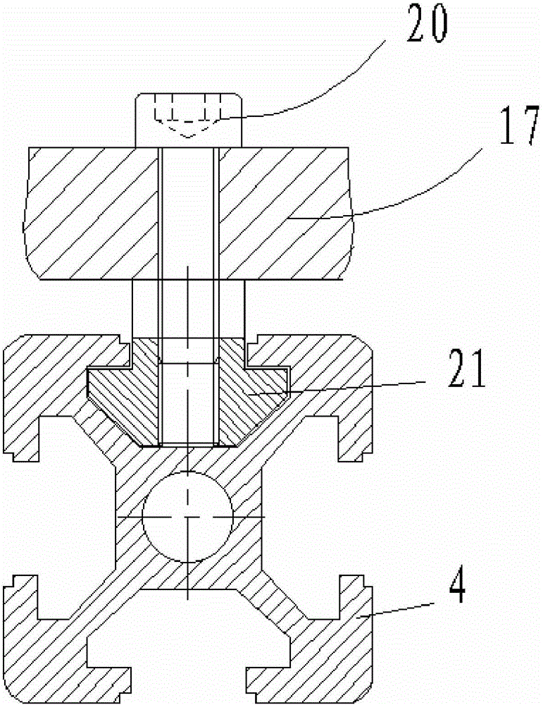
[0024] Such as Figure 1 to Figure 5 As shown, a 3D printer print head walking structure includes a guide rail 4, a synchronous belt 1, a driving pulley 2, and a driven pulley 3. The guide rail 4 is arranged on the top of the printer frame 8, and the driving pulley 2 1. The driven pulley 3 is located at both ends of the guide rail, the driving pulley 2 is connected with the stepping motor 10, the two ends of the timing belt 1 are respectively connected with the driving pulley 2 and the driven pulley 3, and the middle part of the timing belt 1 is connected with the printing head The fixed seat 11 is connected, and the lower part of the fixed seat 11 is connected with the slider 17, and the slider 17 is connected with the guide rail 4. The fixed seat 11 is provided with a printing consuma...


PUM


Abstract

The invention discloses a printing head walking structure of a 3D printer. The printing head walking structure of the 3D printer comprises a guide rail, a synchronous belt, a driving belt wheel and a driven belt wheel. The two ends of the synchronous belt are connected with the driving belt wheel and the driven belt wheel respectively. The synchronous belt is connected with a printing head fixing base. The lower portion of the fixing base is connected with a sliding block. The sliding block is connected with the guide rail. The fixing base is provided with a printing supply feeding motor. A left connecting column and a right connecting column are arranged on the fixing base and located on the left side and the right side of the printing head fixing base respectively. The middle of the synchronous belt is broken, so that a left connecting end and a right connecting end are formed. The left connecting end is connected with the left connecting column. The right connecting end is connected with the right connecting column. The printing head walking structure of the 3D printer is simple; the tension degree of the synchronous belt can be adjusted conveniently, the adjustment precision is high, the service life of the synchronously belt is prolonged, and both use cost and maintenance cost are reduced; the position of the synchronous belt is fixed reliably, looseness is unlikely to occur after the tension degree is adjusted to be proper, the movement smoothness and movement reliability of movable components are kept, and the requirement for precise control over the movement of the components can be met.

Description

technical field [0001] The invention relates to the technical field of 3D printers, in particular to a walking structure of a printing head of a 3D printer. Background technique [0002] The walking structure of the print head of the 3D printer in the prior art widely uses the synchronous belt and the slider guide rail as the structure for transmitting power, and connects the synchronous belt with the printer head to realize the smooth movement of the working parts. The synchronous belt of the prior art is made of plastic material The closed ring-shaped structure is easy to deform due to the plastic material during use, especially under the action of friction and tensile tension in the working process, it is easy to elongate and produce plastic deformation, and it is inconvenient to adjust after deformation. The working parts have poor moving stability and large speed fluctuations, which affect the accuracy of the transmission, thereby affecting the accuracy of the processed...

Claims


Application Information

Patent Timeline
Patent Type & Authority Applications(China)
IPC IPC(8): B29C67/00B33Y30/00
Inventor 隗德民单永磊
Owner UNIV OF JINAN
Why Eureka
Try Eureka