Automatic assembly system of spacecraft cabin on ground

An assembly system and spacecraft technology, applied to ground devices, aircraft assembly, transportation and packaging, etc., can solve problems such as low docking accuracy and poor stability

Active Publication Date: 2015-11-04
BEIJING XINGHANG MECHANICAL ELECTRICAL EQUIP +1
View PDF6 Cites 19 Cited by
  • Summary
  • Abstract
  • Description
  • Claims
  • Application Information

AI Technical Summary

Problems solved by technology

[0005] The purpose of the present invention is to solve the problems of poor stability and low docking accuracy of the current spacecraft ca

Method used


Image

  • Automatic assembly system of spacecraft cabin on ground
  • Automatic assembly system of spacecraft cabin on ground
  • Automatic assembly system of spacecraft cabin on ground

Examples


specific Embodiment approach 1

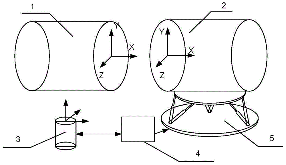
[0075] Specific implementation mode one: combine figure 1 and figure 2 Describe this embodiment, illustrate this embodiment, the automatic assembly system of the spacecraft cabin described in this embodiment on the ground, the assembly system includes a master control system 4, a laser tracker 3 and a parallel mechanism 5;

[0076] The master control system 4 is used to control the laser tracker 3, and according to the position information measured by the laser tracker 3, obtain the positions of the fixed section end face 1, the moving section end face 2 and the parallel mechanism 5 of the cabin section, and according to the obtained position information, Obtain the relative position data of the end surface 1 of the fixed section and the end surface 2 of the moving section through calculation, and control the parallel mechanism 5 according to the relative position data;

[0077] The laser tracker 3 is used to measure the position information of the end face 1 of the fixed se...

specific Embodiment approach 2

[0082] Specific embodiment 2: This embodiment is a further limitation of the automatic assembly system of the spacecraft cabin described in specific embodiment 1 on the ground. The master control system 4, according to the obtained position information, controls the parallel mechanism 5 to include :

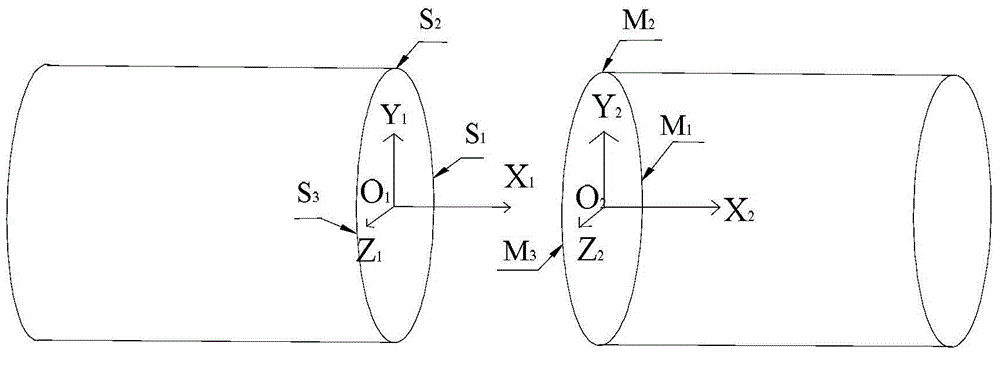
[0083] According to the obtained position information, establish the calibration coordinate system O of the end face 1 of the fixed section 1 -X 1 Y 1 Z 1 and the calibration coordinate system O of the end face 2 of the moving section 2 -X 2 Y 2 Z 2 ;

[0084] According to the obtained position information, establish the parallel mechanism 5 coordinate system O when the parallel mechanism 5 rotates in three dimensions 3 -X 3 Y 3 Z 3 ;

[0085] When the distance between the end face 1 of the fixed segment and the origin of the coordinate system of the end face 2 of the moving segment is greater than or equal to (l+dl)mm, the calibration coordinate system of the end fac...

specific Embodiment approach 3

[0092] Specific implementation mode three: combination image 3 This embodiment is described. This embodiment is a further limitation of the automatic assembly system of the spacecraft cabin section on the ground described in the second specific embodiment. The laser tracker 3 is used to measure the end face 1 and The position information of the end face 2 of the moving section includes:

[0093] After measuring the target ball, output the three-degree-of-freedom coordinates of the center of the target ball;

[0094] Both the end face 1 of the fixed section and the end face 2 of the moving section are planes, and three reference points are respectively selected on the end face 1 of the fixed section and the end face 2 of the moving section, and a target ball is respectively fixed on the selected reference points;

[0095] The master control system 4 establishes the calibration coordinate system O of the end face 1 of the fixed section according to the obtained position inform...


PUM


Abstract

The invention discloses an automatic assembly system of a spacecraft cabin section on the ground, and belongs to the technical field of large-sized space measurement assembly. The automatic assembly system aims to solve the problems that when a conventional spacecraft cabin section is assembled on the ground, the stability is poor, and the abutting precision is low. The assembly system comprises a master control system, a laser tracker and a parallel mechanism, wherein the master control system is used for controlling the laser tracker, obtaining the position of a fixed-section end surface of the cabin section, the position of a movable-section end surface of the cabin section, and the position of the parallel mechanism according to position information measured by the laser tracker, obtaining the relative position data of the fixed-section end surface and the movable-section end surface through calculation according to the obtained position information, and controlling the parallel mechanism according to the relative position data; the laser tracker is used for measuring the position information of the fixed-section end surface, the position information of the movable-section end surface, and the position information of the parallel mechanism by utilizing a T-Probe or a target sphere; the parallel mechanism is used for controlling the motion of the movable section of the cabin section according to the control of the master control system. The assembly system disclosed by the invention is used for spacecraft production.

Description

technical field [0001] The invention belongs to the technical field of large-scale space measurement and assembly. Background technique [0002] Modern aircraft, rockets, and missiles have a large number of components, complex shapes, and thin and easily deformed structures, making their assembly a complex project with great difficulty and multiple fields of design. The assembly process largely determines the final quality, manufacturing cost and production cycle of aircraft, rockets and missiles. [0003] At present, the docking and separation of most large-scale spacecraft sections is carried out in a vertical state. Its safety and quality mainly depend on the engineering experience of the craftsmen and the individual skill level of the operators, and the stability and accuracy of the docking cannot be guaranteed. [0004] Large-scale space measurement and assembly technology has played an irreplaceable and important role in the automated production process of aircraft, r...

Claims


Application Information

Patent Timeline
IPC IPC(8): B64F5/00B64F5/10
Inventor 戴勇波齐乃明刘延芳张强张丹丹赵一鸣马明阳
Owner BEIJING XINGHANG MECHANICAL ELECTRICAL EQUIP
Why Eureka
Try Eureka