
Automatic handle feeding device of handle installing machine

A machine-installed and automatic technology, applied in packaging and other directions, can solve the problems of easy contamination of operators and handles, low feeding efficiency, easy scratches of handles, etc., and achieve the effect of simple structure, high production efficiency and low labor intensity

Inactive Publication Date: 2015-11-04
池州睿欣碳纤维科技有限公司
View PDF0 Cites 3 Cited by
  • Summary
  • Abstract
  • Description
  • Claims
  • Application Information

AI Technical Summary

Problems solved by technology

[0003] The technical problem to be solved by the present invention is to provide an automatic handle feeding device of a handle installation machine to solve the problems of low efficiency of traditional manual feeding, easy scratching of the handle by the operator and easy contamination of the handle

Method used


Image

  • Automatic handle feeding device of handle installing machine
  • Automatic handle feeding device of handle installing machine
  • Automatic handle feeding device of handle installing machine

Examples


Embodiment Construction

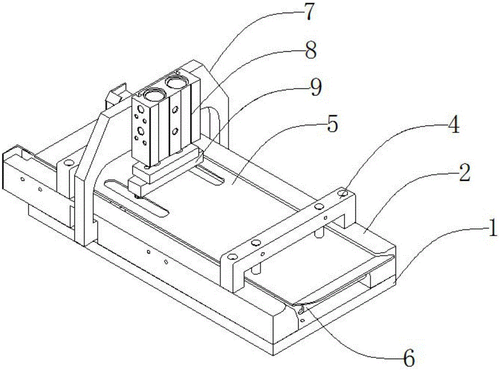
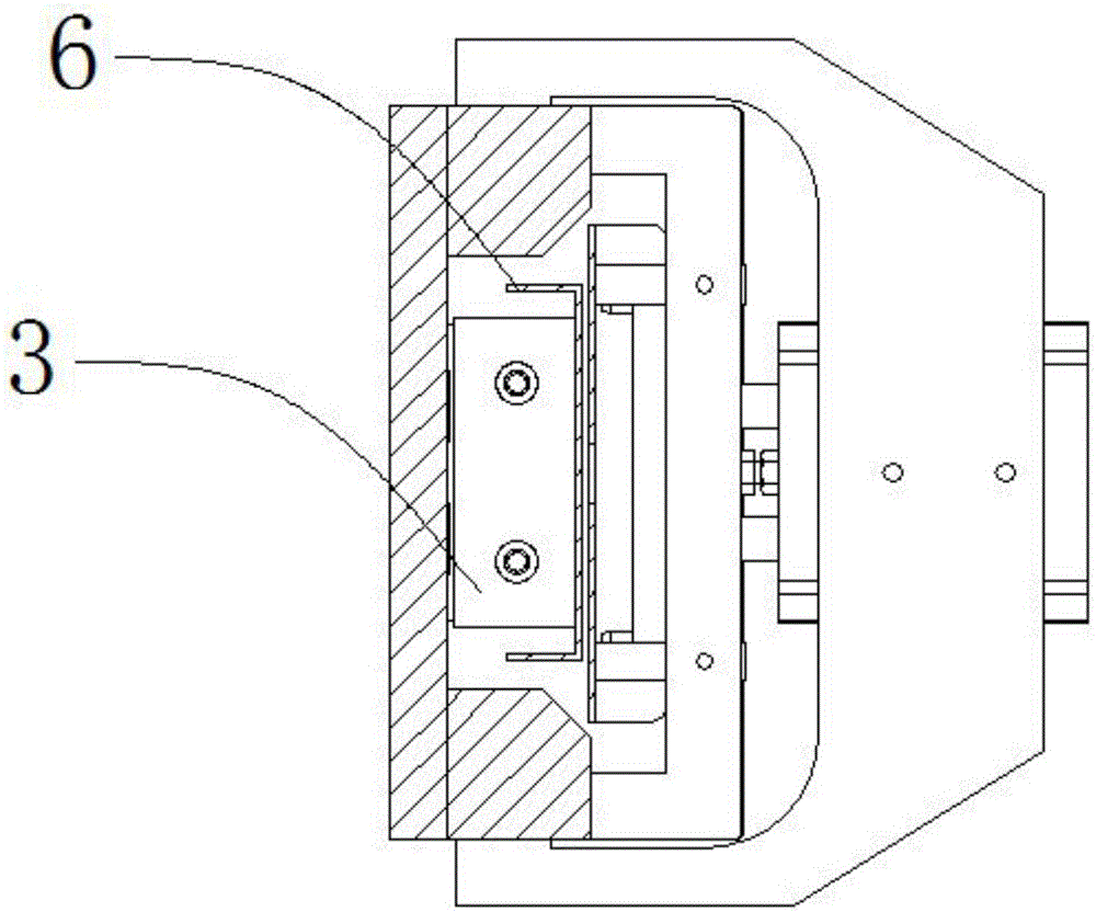
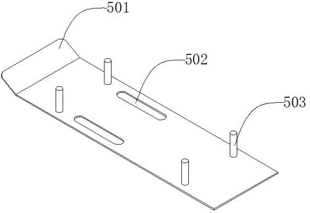
[0025] Such as figure 1 , figure 2 , image 3 , Figure 4 , Figure 5 As shown, an automatic handle delivery device of a handle installation machine includes a bottom plate 1, a vertical plate 2, a first cylinder 3, a pressure plate bracket 4, a pressure plate 5, a handle supporting plate 6, a pressure handle frame 7, The second cylinder 8, the handle block 9, the vertical plate 2 is arranged symmetrically with the upper end of the bottom plate 1, the vertical plate 2 is threadedly connected with the bottom plate 1, and the first cylinder 3 is located at the upper end of the bottom plate 1. The first cylinder 3 is threadedly connected with the bottom plate 1, the pressure plate bracket 4 is located at the upper end of the vertical plate 2, the described pressure plate bracket 4 is threaded with the vertical plate 2, the described pressure plate 5 is located at the lower end of the pressure plate bracket 4, and the The pressing plate 5 is threadedly connected with the pres...


PUM


Abstract

The invention discloses an automatic handle feeding device of a handle installing machine. The device comprises a baseplate, and further comprises a stand plate, a first cylinder, a pressure plate bracket, a pressure plate, a handle support plate, a handle pressure frame, a second cylinder and a handle pressure block. The device is simple in structure, can automatically and continuously convey handles, only needs operators to control the machine, and is low in labor intensity and high in production efficiency; and as the operators have no need to touch the handles, the handles are not polluted, and the operators are not scratched by the handles.

Description

technical field [0001] The invention relates to an auxiliary device of a handle installation machine, in particular to an automatic handle feeding device of the handle installation machine. Background technique [0002] At present, with the development of industry, the demand for paper packaging boxes is also increasing, and the demand for manufacturing paper packaging boxes is also increasing. The traditional handle installation device uses manual feeding, which is not only low in efficiency and high in strength, but also The handle is easy to scratch fingers, and moreover, the hand directly touches the handle and easily causes the pollution of the handle. In view of the above-mentioned defects, it is really necessary to design a kind of automatic handle delivery device of the handle installation machine. Contents of the invention [0003] The technical problem to be solved by the present invention is to provide an automatic handle feeding device of a handle installation...

Claims


Application Information

Patent Timeline
Patent Type & Authority Applications(China)
IPC IPC(8): B65B61/14
CPCB65B61/14
Inventor 鲍定胜
Owner 池州睿欣碳纤维科技有限公司
Learn More