Discharge device roller structure

A discharge drum and drum technology, applied in the field of discharge drum, can solve the problems of affecting the quality of finished products and uneven raw and cooked clinker, and achieve the effect of improving the uniformity of discharge, improving the quality of finished products, and overcoming the side wall effect

Active Publication Date: 2015-11-04
ACRE COKING & REFRACTORY ENG CONSULTING CORP DALIAN MCC
View PDF7 Cites 9 Cited by
  • Summary
  • Abstract
  • Description
  • Claims
  • Application Information

AI Technical Summary

Problems solved by technology

Although the discharge drum of the existing discharge device can simultaneously discharge materials along the length direction of the retort chamber, due to the "side wall effect" between the material and the end wall of the retort chamber, the feeding speed in the middle of the retort chamber length direction is always It is greater than the feeding speed at both ends, so that the temperature in the retort chamber along the length direction is distributed in a "V" shape curve with a low middle and high sides. This temperature distribution is likely to cause uneven raw and cooked clinker and affect the quality of the finished product.

Method used


Image

  • Discharge device roller structure
  • Discharge device roller structure
  • Discharge device roller structure

Examples


Embodiment Construction

[0019] The specific embodiment of the present invention will be further described below in conjunction with accompanying drawing:

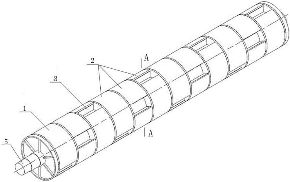
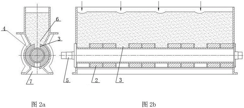
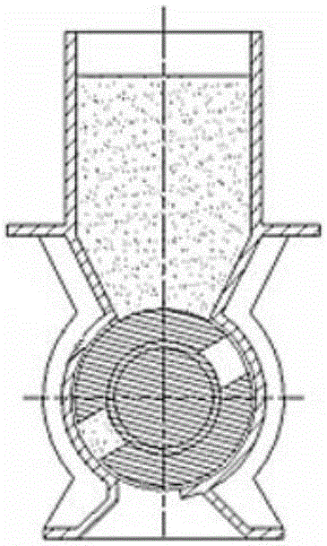
[0020] See figure 1 , is a structural schematic diagram of the present invention, a drum structure of a discharge device of the present invention, including a discharge drum 1, and the discharge drum 1 is composed of a plurality of single row drums 2 arranged axially on a rotating shaft 5, each single row Several hoppers 3 are evenly arranged on the drum 2 along the circumferential direction, and each single-row drum 2 is arranged alternately along the same direction; that is, the hoppers 3 on the entire discharge drum 1 are arranged in multiple parallel helical lines along the axial direction.

[0021] The single-row rollers 2 are sequentially arranged at the same staggered angle.

[0022] The hoppers 3 have the same shape and size; the angle between the centerlines of adjacent hoppers 3 on the same single-row drum 2 is larger than the opening a...


PUM


Abstract

The invention relates to a discharge device roller structure which comprises a discharge roller, wherein the discharge roller is composed of a plurality of single roller rows which are arranged along the axial direction of the rotating shaft; each single roller row is uniformly provided with a plurality of hoppers in the circumference direction; all the single roller rows are sequentially arranged in a staggered mode in the same direction; and thus, the hoppers on the whole discharge roller in the corresponding positions are arranged along a plurality of parallel spiral lines in the axial direction. Compared with the prior art, when being used in a continuous retort furnace, the discharge device roller structure can enhance the discharge uniformity, optimizes the discharged material surface curve into small waves from V shape, overcomes the influence of wall effect during material down-going, and enhances the end product quality of clinker.

Description

technical field [0001] The invention relates to a discharge drum, in particular to a drum structure of a discharge device used in a continuous retort furnace. Background technique [0002] In the production process of the continuous retort furnace, the discharge device is a device used to discharge the cooled clinker from the retort chamber. Although the discharge drum of the existing discharge device can simultaneously discharge materials along the length direction of the retort chamber, due to the "side wall effect" between the material and the end wall of the retort chamber, the feeding speed in the middle of the retort chamber length direction is always The feeding speed is greater than that at both ends, so that the temperature in the retort chamber along the length direction is distributed in a "V" shape curve with a low middle and high sides. This temperature distribution is likely to cause uneven raw and cooked clinker and affect the quality of the finished product. ...

Claims


Application Information

Patent Timeline
Patent Type & Authority Applications(China)
IPC IPC(8): C10B33/00F27D3/00
Inventor 刘洪春刘淳刘承智龚俊库杜刚刘玉虎赵国峰
Owner ACRE COKING & REFRACTORY ENG CONSULTING CORP DALIAN MCC
Why Eureka
Try Eureka