U-shaped steel-structure formwork

A technology of structural formwork and U-shaped steel, which is applied in the field of civil engineering, can solve the problems of scaffolding taking a lot of time, and achieve the effect of ensuring stability, facilitating hoisting, and anchoring steel bars

Inactive Publication Date: 2015-11-04
SHANGHAI MUNICIPAL ENG DESIGN INST GRP
View PDF7 Cites 2 Cited by
  • Summary
  • Abstract
  • Description
  • Claims
  • Application Information

AI Technical Summary

Problems solved by technology

[0002] At present, the pouring of concrete beams generally requires the erection of scaffolding, especially when pouring high-altitude and long-span concrete beams, the erection of scaffolding takes a lot of time

Method used


Image

  • U-shaped steel-structure formwork

Examples


Embodiment Construction

[0018] The present invention will be further elaborated below by describing a preferred specific embodiment in detail in conjunction with the accompanying drawings.

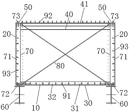
[0019] Such as figure 1 As shown, a U-shaped steel structure formwork is used for pouring concrete beams, especially suitable for the construction of large-span and high-altitude concrete hollow box girders. The U-shaped steel structure formwork includes: a bottom steel plate 10 and two side steel plates 20, The bottom steel plate 10 and two side steel plates 20 are spliced ​​together to form a U shape; several lower H-shaped steel beams 30 are arranged at intervals above the bottom steel plate 10 along the length direction of the bottom steel plate 10, and the lower The web 31 of the H-shaped steel beam 30 is perpendicular to the bottom steel plate 10; several upper H-shaped steel beams 40 are correspondingly arranged above the lower H-shaped steel beam 30, and the upper part of the upper H-shaped steel beam 40 ...


PUM


Abstract

The invention discloses a U-shaped steel-structure formwork which is used for pouring concrete beams. The U-shaped steel-structure formwork comprises a bottom steel plate, two side steel plates, a plurality of lower H-shaped steel beams and a plurality of upper H-shaped steel beams. A U shape is formed by splicing the bottom steel plate and the two side steel plates. The lower H-shaped steel beams are arranged on the bottom steel plate at intervals in the length direction of the bottom steel plate, webs of the lower H-shaped steel beams are perpendicular to the bottom steel plate, the upper H-shaped steel beams are correspondingly arranged on the lower H-shaped steel beams, upper wing plates of the upper H-shaped steel beams are connected with the two side steel plates through two top steel plates respectively, and webs of the upper H-shaped steel beams are perpendicular to the bottom steel plate. A reinforcement cage can be rolled in advance on the ground, the concrete beams can be directly formed in the formwork through pouring after the steel-structure formwork is hung, and therefore the construction quality can be effectively ensured, no scaffold needs to be erected any more, the construction period can be shortened, and good economic benefits are achieved.

Description

technical field [0001] The invention relates to the technical field of civil engineering, in particular to a U-shaped steel structure template. Background technique [0002] At present, the pouring of concrete beams generally requires the erection of scaffolding, especially when pouring high-altitude and long-span concrete beams, the erection of scaffolding takes a lot of time. Contents of the invention [0003] The purpose of the present invention is to provide a U-shaped steel structure formwork, which can complete the rolling of the steel cage on the ground in advance, and after the steel structure formwork is hoisted, concrete beams can be directly poured inside the formwork, which can not only effectively ensure construction Quality, and there is no need to erect scaffolding, which can shorten the construction period and have good economic benefits. [0004] In order to achieve the above object, the present invention is realized through the following technical soluti...

Claims


Application Information

Patent Timeline
Patent Type & Authority Applications(China)
IPC IPC(8): E04G13/04
Inventor 杨龙
Owner SHANGHAI MUNICIPAL ENG DESIGN INST GRP
Why Eureka
Try Eureka