
Axicon beam scanning device

A technology of rotating axicon and beam scanning, which is applied in the field of optical scanning systems, can solve the problems of cogging customization cost, affecting driving accuracy, and difficult space layout, etc., and achieve simple and reliable connection relationships, improve transmission accuracy, and reduce error transmission links. Effect

Inactive Publication Date: 2018-10-26
TONGJI UNIV
View PDF10 Cites 2 Cited by
  • Summary
  • Abstract
  • Description
  • Claims
  • Application Information

AI Technical Summary

Problems solved by technology

[0007] The prior technology (Zu Jifeng and other patents, application number: 03129234.8, application date June 13, 2003 "Satellite trajectory optical simulation device") proposes a scheme of motor group and gear transmission to realize different motion matching modes of the rotating double prism, but The complex motor combination and control system will affect the driving accuracy and bring difficulties in space layout
[0008] Prior technology (Sun Jianfeng and other patents, application number: 200410024986.2, application date October 2004 "High-precision dynamic and static measurement device for inter-satellite laser communication terminals") directly couples the torque motor with the rotating shaft to realize the yaw movement of the orthogonal prism , but this method faces the problems of torque fluctuation, cogging effect and customization cost when it is applied to the rotating prism
[0009] The prior technology (Patent by Li Anhu, etc., application number: 201310072421.0, application date: March 7, 2013 "Synchronous Belt Driven Rotating Prism Device") uses a synchronous belt device to drive the rotation of a large-diameter prism, with accurate transmission ratio, low noise, and excellent structure Compactness and other advantages, but at the same time, there may also be phenomena such as material aging, fatigue wear, and tooth climbing and skipping.

Method used


Image

  • Axicon beam scanning device
  • Axicon beam scanning device
  • Axicon beam scanning device

Examples


example

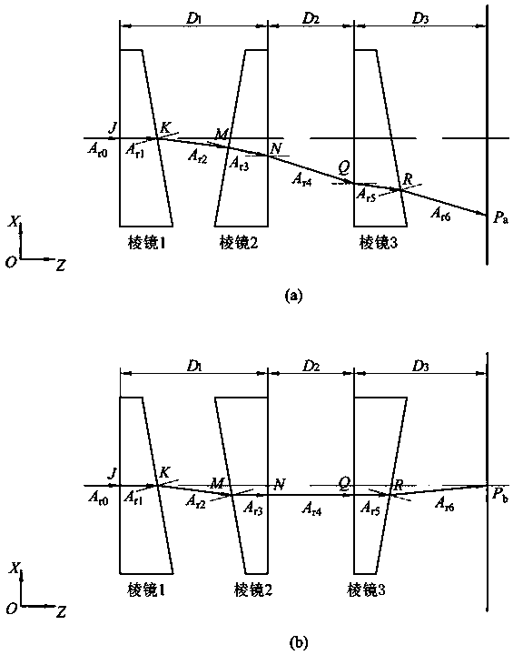
[0054] Set the prism to have exactly the same parameters: α =10°, n =1.517, d 0 =5 mm, D p =80 mm; and D 1 =100mm, D 2 =100 mm, D 3 =100 mm. Under this condition, the scanning domain radius of the rotating double prism system composed of only the first wedge prism and the second wedge prism is R d =45.4892 mm, the radius of the blind zone is R dbz=7.1207 mm; while the scanning field radius of the axicon system composed of the first wedge prism, the second wedge prism and the third wedge prism at the same position is R t =53.0426 mm, the radius of its blind zone becomes R tbz =0 mm. Therefore, the expansion rate of the scanning domain caused by the third wedge prism is δ=[ R t 2 -( R d 2 - R dbz 2 )] / ( R d 2 - R dbz 2 )=39.38%, and the expansion effect of the newly added prism on the scanning domain will follow D 3 growth has become more pronounced. In addition, it can be further determined that the critical distance to eliminate the blind zo...


PUM


Abstract

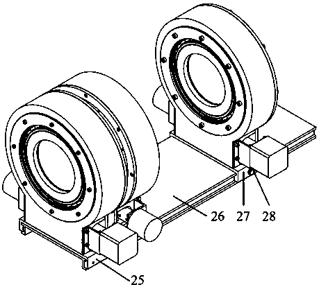
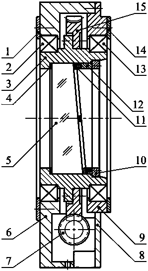
The invention relates to a rotating triple-prism beam scanning device comprising a rotating double-prism system, a rotating single-prism system, a guide rail, an adjustable support, and a fixed support. The rotating single-prism system comprises a base component, a prism and frame assembly, and a worm-and-gear mechanism. The prism and frame assembly comprises a flat washer, a wedge prism, a rubber pad, a wedge retainer ring, a threaded retainer ring, and a frame. The base component comprises a base, a base baffle, and a base insert. The worm-and-gear mechanism comprises a rotary motor, a motor stand, a coupling, a worm, a bearing support, a rolling bearing, a worm gear, an encoder support, and a rotary encoder. The rotating double-prism system is formed by assembling two rotating single-prism systems together. In the invention, the three wedge prisms are driven by the worm-and-gear mechanisms to do full-circumferential rotation, transmission is stable and accurate, and the scanning precision and stability of dynamic beams can be ensured; the prisms are independent of one another in rotation control, and diversified scanning modes can be achieved; and by introducing the third prism to the double-prism system, the scanning field of beams is enlarged significantly, and the problem that a double-prism system has scanning blind areas and control singular points is solved effectively.

Description

technical field [0001] The invention relates to an optical scanning system, in particular to an axicon beam scanning device. Background technique [0002] As a common optical transmission system, the beam scanning mechanism can be divided into two types: reflection type and refraction type according to the different scanning optical elements used. The reflective beam scanning mechanism is limited by its complex system structure and limited scanning accuracy, and is generally used in occasions with low performance requirements. The refraction beam scanning mechanism is based on the law of refraction of light. It can realize high-precision beam deflection and optical path compensation through the continuous rotation of a single prism, or obtain an enlarged beam scanning field of view and rich beam scanning trajectories through the combination of multi-prisms. has received widespread attention. [0003] (1) The following prior art shows the main fields of application of the r...

Claims


Application Information

Patent Timeline
Patent Type & Authority Patents(China)
IPC IPC(8): G02B26/12
CPCG02B26/121G02B26/124
Inventor 李安虎刘兴盛卞永明刘广军
Owner TONGJI UNIV
Learn More