
Secondary mirror supporting structure of space optical remote sensing camera

A technology of space optical remote sensing and secondary mirror support, applied in the field of space optical remote sensing, can solve the problems of heavy support structure, large width of truss rods, and large obscuration ratio, etc., and achieves small obscuration, high lightweight rate, and small self-weight deformation. Effect

Inactive Publication Date: 2018-10-12
CHANGGUANG SATELLITE TECH CO LTD
View PDF0 Cites 19 Cited by
  • Summary
  • Abstract
  • Description
  • Claims
  • Application Information

AI Technical Summary

Problems solved by technology

[0003] In order to solve the technical problems of traditional support structures such as heavy weight, low specific stiffness, large truss bar width, and large blocking ratio, the present invention provides a secondary mirror support structure for space optical remote sensing cameras

Method used


Image

  • Secondary mirror supporting structure of space optical remote sensing camera
  • Secondary mirror supporting structure of space optical remote sensing camera
  • Secondary mirror supporting structure of space optical remote sensing camera

Examples


specific Embodiment 1

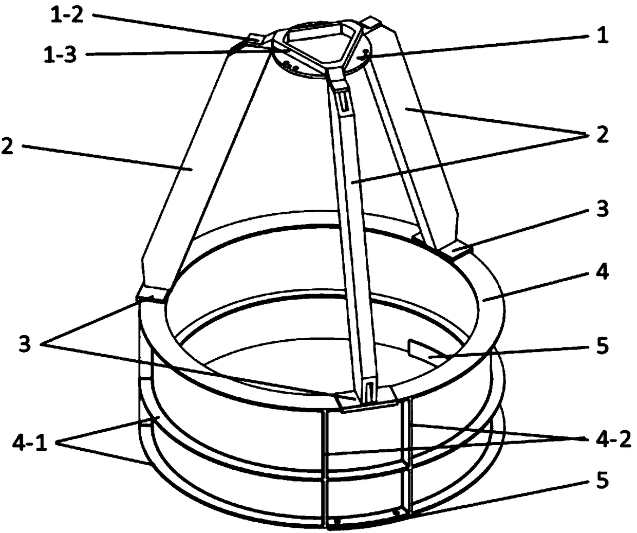
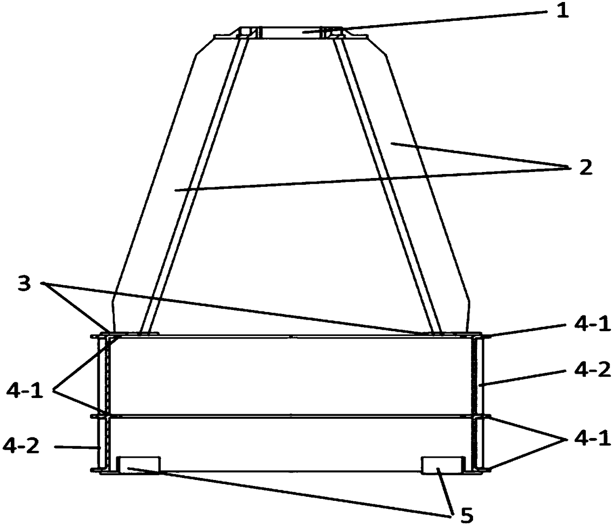
[0038] Specific embodiment one: as figure 1As shown, the number of the truss rod 2, the embedded part 5 and the circumferential rib 4-1 on the outer wall of the truss base 4 are three, and the circumferential rib 4-1 on the inner wall of the truss base 4- The number of 1 is two, and it corresponds to the two circumferential ribs 4-1 on the upper end of the outer wall of the truss base 4. The shape of the circumferential reinforcing rib 4-1 of the barrel seat is circular, and the diameters of the circumferential reinforcing ribs 4-1 of the barrel seat are the same. The three truss rods 2 and the three embedded parts 5 are evenly distributed in a circle of 120 degrees in the support structure. The number of groups of axial reinforcing ribs 4-2 on the outer wall of the truss cylindrical seat 4 is three groups, and the number of axial reinforcing ribs 4-2 in each group of cylindrical seat is two.

[0039] The shape of the flange 1 is circular, and the ribs 1-3 of the flange are ...


PUM


Abstract

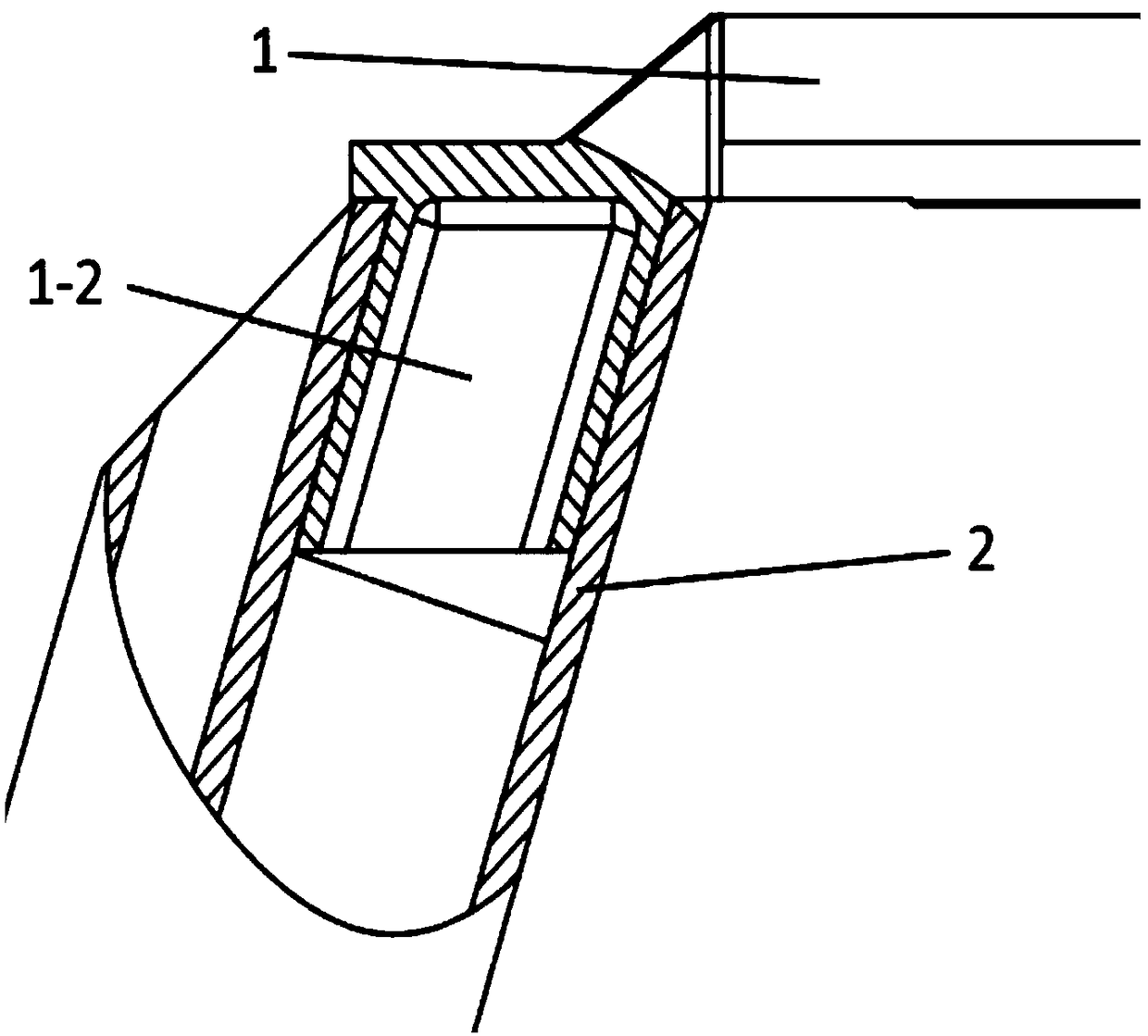
The invention provides a secondary mirror supporting structure of a space optical remote sensing camera, belongs to the technical field of space optical remote sensing, and aims at solving the technical problems that the conventional supporting structure has high weight, low specific stiffness, high truss rod width and high obscuration ratio. One surface of the flange is evenly provided with multiple flange bosses. The edge of the same surface is evenly provided with multiple flange embedding connectors. The cross section of the truss rods is shaped like a Chinese character "ri". One end of each truss rod is connected with the top part of a truss cylinder base through a truss rod embedding connector, and the other end is connected with the flange through one flange embedding connector. Multiple pre-embedded members are fixed on the bottom part of the truss cylinder base. The structural stiffness can be strengthened and the advantages of stable structure and low gravity deformation canbe realized by the ring enforcing ribs arranged in the truss cylinder base, and the stray light shading capacity can also be provided. The cross section of the truss rods is shaped like the Chinese character "ri" so that the advantages of low obscuration, high stiffness and high lightweight rate can be realized.

Description

technical field [0001] The invention belongs to the technical field of space optical remote sensing, and relates to a secondary mirror support structure made of carbon fiber composite material with stable structure and small obstruction. Background technique [0002] In the space camera of the Cassegrain optical system, the secondary mirror and its supporting structure are located at the light entrance, the distance between the primary and secondary mirrors is relatively large, and the installation accuracy of the secondary mirror is high. Vibration response and so on have strict requirements. The traditional cylindrical structure has heavy weight, low specific stiffness, and duplicates the shading function provided by the whole star structure; the traditional truss structure has a large width of the truss rods, a large blocking ratio, or a large number of truss rods and a complex structure, resulting in a large amount of diffracted energy, and does not It is convenient for...

Claims


Application Information

Patent Timeline
IPC IPC(8): G02B7/182G03B17/12G03B17/17
CPCG02B7/182G03B17/12
Inventor 李凯宋可心王升李季贾学志
Owner CHANGGUANG SATELLITE TECH CO LTD
Learn More