
Light source device

A light source device and light source technology, applied in the direction of light source, lighting device, point light source, etc., can solve the problems of uneven illumination, difficulty for LED to meet lighting standards, glare, etc., and achieve the effect of reducing visual impact and good and comfortable light environment

Inactive Publication Date: 2015-11-04
IND TECH RES INST
View PDF4 Cites 7 Cited by
  • Summary
  • Abstract
  • Description
  • Claims
  • Application Information

AI Technical Summary

Problems solved by technology

[0003] However, LEDs usually output directly in the Lambertian light type, so the light intensity of the central viewing angle is strong and the light intensity of the peripheral viewing angle is weak. When it is applied to lighting, it often produces spots with uneven illumination. And it is easy to have a large angle (such as ±45° or more) that deviates from the normal direction of the light source to enter the human eye and cause glare, which will make it difficult for LEDs to meet the requirements of lighting regulations

Method used


Image

  • Light source device
  • Light source device
  • Light source device

Examples


Embodiment Construction

[0061] In order to make the object, technical solution and advantages of the present invention clearer, the present invention will be further described in detail below in conjunction with specific embodiments and with reference to the accompanying drawings.

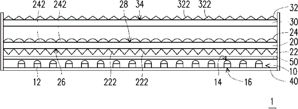
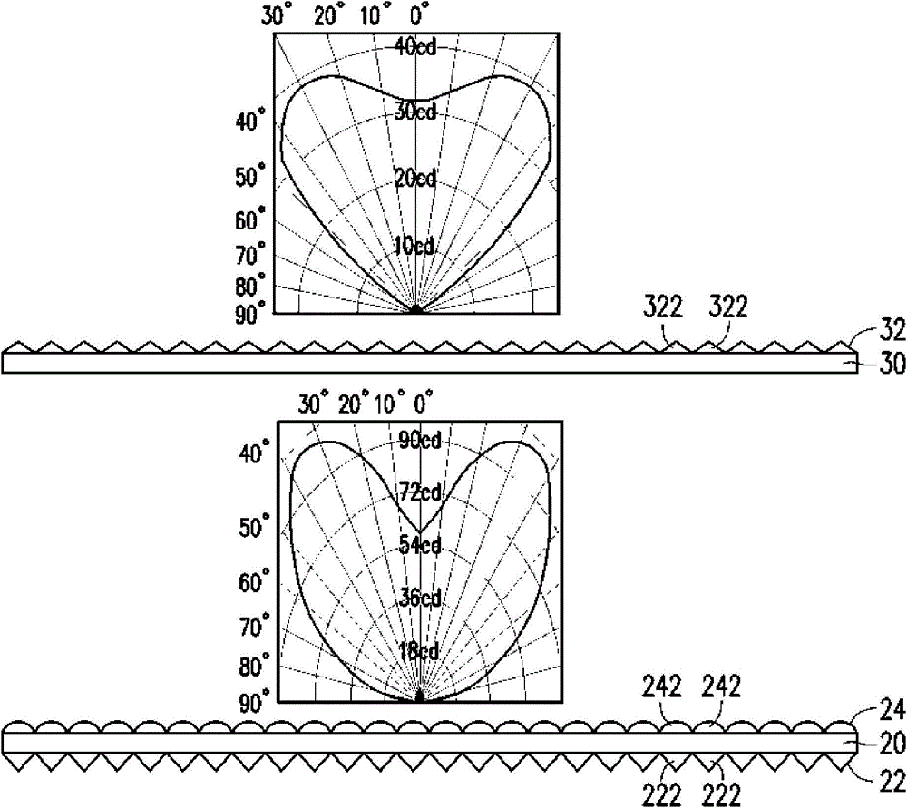
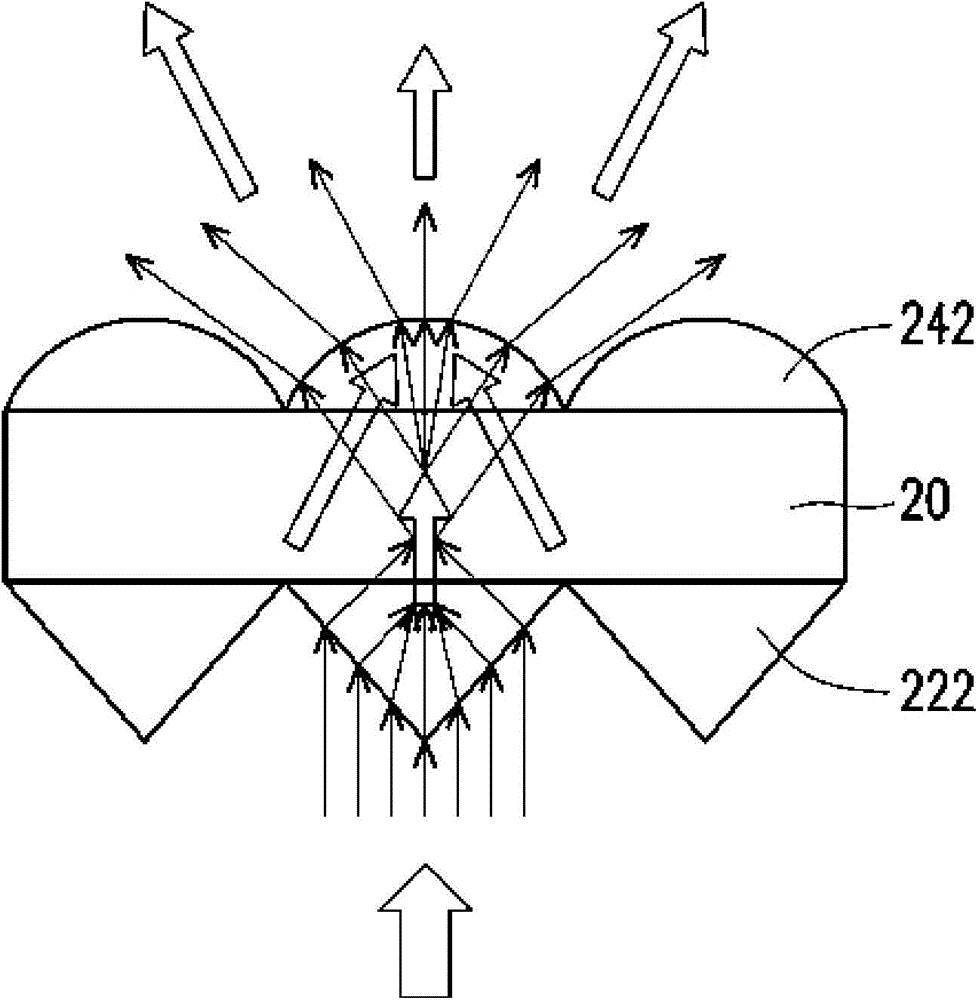
[0062] Please refer to figure 1 , which is a schematic cross-sectional view of a light source device according to an embodiment of the present invention. The light source device 1 includes a light source 10 , a batwing optical film 20 and a glare control film 30 . The light source 10 includes at least one light emitting element 12 . In this embodiment, the light source 10 is composed of a plurality of light emitting elements 12 arranged in an array, wherein each light emitting element 12 has a light emitting surface 14 . The batwing light optical film 20 has a first microstructure layer 22 and a second microstructure layer 24, which are respectively arranged on the first surface 26 and the second surface 28 opposite to t...


PUM


Abstract

The present invention discloses a light source device comprising a light source, a light bat-wing type optical film and a glare control film. The light source comprising at least one light emitting element, having a glossy. The bat-wing light control type optical film having a first microstructure layer and a second microstructure layer, are disposed in the bat wing light type optical film opposite to a first surface and a second surface, wherein the first surface is exit surface facing the light-emitting elements. The microstructure of the first layer comprises a plurality of first prism type structure, and the second microstructure layer comprises a plurality of cylindrical lenses. The glare control film having a third microstructured layer disposed on a third surface glare control film, wherein the third surface is a smooth back to the light emitting element, the third layer comprises a plurality of second microstructured prism type structure, and the bat-wing light optical film is disposed between the light source and the glare control film.

Description

technical field [0001] The invention relates to a light source device, in particular to a light source device applied to lighting. Background technique [0002] White light-emitting diodes (Light-Emitting Diodes, LEDs) have the advantages of high lumen efficiency, low energy consumption, high reliability, and long life, and are gradually being used in daily life. [0003] However, LEDs usually output directly in the Lambertian light type, so the light intensity of the central viewing angle is strong and the light intensity of the peripheral viewing angle is weak. When it is applied to lighting, it often produces spots with uneven illumination. And it is easy to have a large angle (such as ±45° or more) that deviates from the normal direction of the light source to enter the human eye and cause glare, which will make it difficult for LEDs to meet the requirements of lighting regulations. Therefore, how to redistribute the energy of the light field shape through primary optic...

Claims


Application Information

Patent Timeline
Patent Type & Authority Applications(China)
IPC IPC(8): F21V5/02F21V5/04F21V13/00F21Y101/02
Inventor 廖启宏郑陈嶔
Owner IND TECH RES INST
Learn More