
Process for biostabilization and humification of biological sludge in planted filtering beds

A technology of biological sludge and stabilization method, applied in chemical instruments and methods, biological water/sewage treatment, sustainable biological treatment, etc., can solve the problems of liquid accumulation and low efficiency

Inactive Publication Date: 2010-03-31
ACQUE +1
View PDF0 Cites 6 Cited by
  • Summary
  • Abstract
  • Description
  • Claims
  • Application Information

AI Technical Summary

Problems solved by technology

[0013] However, these methods are inefficient, mainly because of the following problems: clogged drainage layer leads to excessive accumulation of liquid at the bottom of the drainage layer and consequent extreme anaerobic activity

Method used


Image

  • Process for biostabilization and humification of biological sludge in planted filtering beds
  • Process for biostabilization and humification of biological sludge in planted filtering beds
  • Process for biostabilization and humification of biological sludge in planted filtering beds

Examples


Embodiment 1

[0084] In the purification plant where the measurements were made, the amount of sludge produced by 3,000 equivalent inhabitant (e.i.) was treated, which generated about 1,200m 3 / year (2% solids) of biological sludge.

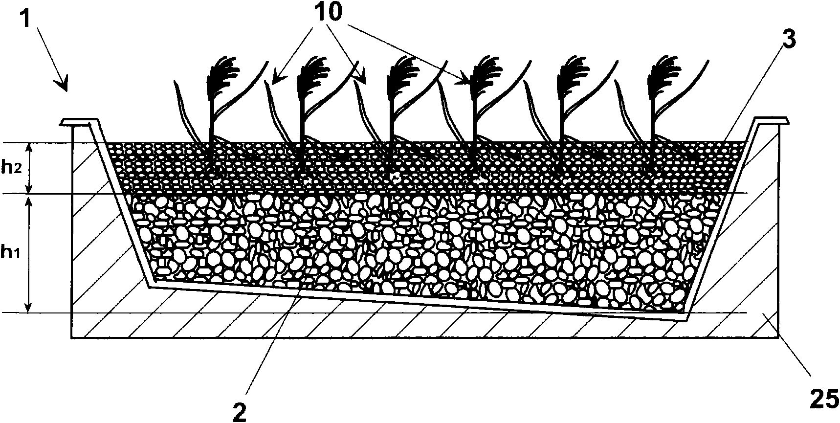
[0085] For the phytostabilization method, a size of 10m x 2.5m x 0.7m with a capacity of 17.5m was used 3 six sludge drying beds. Of these beds, only 4 were used for experiments, while the remaining two were left unused and kept in reserve for possible plant emergencies. The bottom layer of the plant drying bed consisted of drainage material (25 cm of gravel with a diameter of 40-70 mm and 15 cm of gravel with a diameter of 0.5 cm) in which perforated conduits were placed for collecting leachate.

[0086] In May 2004, reed seedlings were placed in an intermediate layer between larger gravel and smaller gravel in the number of about 140 per basin. In order to ensure the development and growth of the plants, fresh water followed by nutrient-rich water from a ...

Embodiment 2

[0089] Prepared with a total volume of 864m 3 12 drying ponds. For a total of 6652m generated in the method 3 Sludge (30000e.i.) used about 4,500m per year 3 sludge.

[0090] The step of planting seedlings in the bed was carried out at the end of July, 2005, and the occupied area of ​​each plant was 0.5m×0.5m. After a period of about one month for the seedlings to acclimatize and grow, to which they were supplied with water from the plant to reduce stress from transplanting and to help better rooting, the first layer of sludge was poured in September 2005, The first samples were then taken in early October 2005 and the plant continued to operate. During the first year of operation, the volume of sludge was reduced by 99% at a rate of 2.42 cubic meters per square meter.

Embodiment 3

[0092] Identical with embodiment 2, its difference is that preparing total volume is 225m 3 of 5 drying pools. For a total of 5616m generated in the method 3 Sludge (10000e.i.) uses about 1462m per year 3 sludge. During the first year of operation, the volume of sludge poured was reduced to 98% at a rate of 3.16 cubic meters per square meter.


PUM

PropertyMeasurementUnit
particle sizeaaaaaaaaaa
heightaaaaaaaaaa
particle sizeaaaaaaaaaa

Abstract

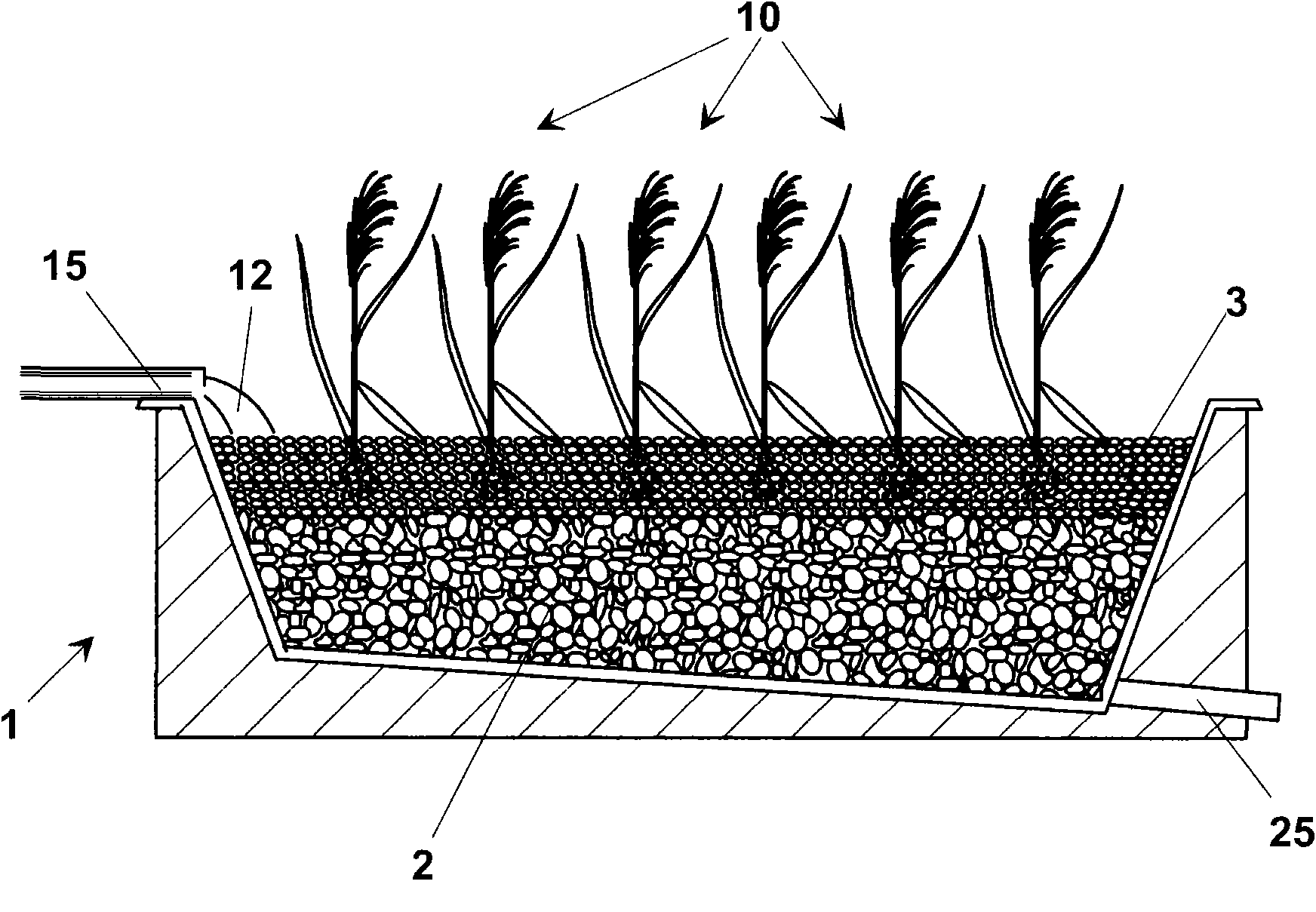
A process for stabilization of biological sludge provides the step of laying in a containing volume, or basin (1), a draining material (2). In particular, the layer of draining material (2) can be a layer of gravel having granulometry set between 40 and 70 mm and a height (hi) about 25 cm. On the first layer (2) a second draining layer (3) can be laid comprising a material, for example gravel having granulometry less than the first layer (2), set between 4 and 6 mm. The second layer (3) has preferably a height (h2) about 15 cm. Once made the draining layers (2, 3) a planting step is made in the second layer (3) of a plurality of seedlings of an aquatic macrophyte, preferably Phragmites australis (10). The base granular filtering gravel layer has also the function of supporting the root ofthe seedlings. To ensure a high efficiency of the process a measured density of plants is chosen, corresponding to a relative distance between two seedlings of Phragmites australis set between 40 and60 cm. once achieved a measured vegetative growth, a first spilling in the containing volume (1) is carried out of an amount of biological sludge (12). The amount of sludge (12) fed in the containingvolume (1) corresponds to a predetermined height, set between 2 and 4 cm, of the layer of sludge (12) on the draining layer (3).

Description

technical field [0001] The present invention relates to a method for stabilizing industrial or municipal sludge, in particular by means of "in situ" treatment. Background technique [0002] It is well known that the treatment of biological sludge produced by purification plants is economically and operationally critical to the management of industrial and municipal wastewater treatment plants. [0003] In fact, sludge represents the main waste of various purification plants, and the choice of whether to treat or recycle sludge is extremely important for the balance of plant operations as well as their environmental impact. [0004] Depending on the nature of the sludges, they can be treated in many ways. [0005] If the sludge comes from the purification of industrial wastewater, it can be disposed of in a special dump. However, before disposal, the sludge must be converted into a loose dewatered material by mechanical dewatering through a filter press and then mixed with ...

Claims


Application Information

Patent Timeline
Patent Type & Authority Applications(China)
IPC IPC(8): C02F11/16C02F3/32C05F17/00
CPCC02F11/16C02F3/327Y02W10/10Y02W30/40
Inventor 马西莫·艾洛保罗·佩鲁齐布鲁洛·切坎蒂格拉齐亚·马斯安达洛罗科·斯图切奥马尔科·阿尔比埃莱诺拉·佩鲁齐
Owner ACQUE
Learn More