
Antenna structure and clockwork with antenna structure

An antenna structure, a technology for a clock device, which is applied to antenna supports/mounting devices, clocks, radio-controlled timers, etc., and can solve problems such as affecting antenna radiation performance.

Active Publication Date: 2015-11-04
SHENZHEN FUTAIHONG PRECISION IND CO LTD +1
View PDF8 Cites 1 Cited by
  • Summary
  • Abstract
  • Description
  • Claims
  • Application Information

AI Technical Summary

Problems solved by technology

However, when the watch device uses a metal body or a strap, the radiation performance of the antenna will inevitably be affected by the metal shielding effect. At the same time, the antenna is designed at the strap position and is susceptible to interference from the wrist, which affects the antenna radiation performance.

Method used


Image

  • Antenna structure and clockwork with antenna structure
  • Antenna structure and clockwork with antenna structure
  • Antenna structure and clockwork with antenna structure

Examples


Embodiment Construction

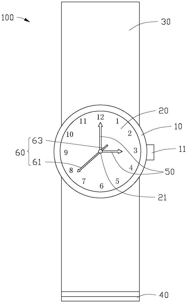
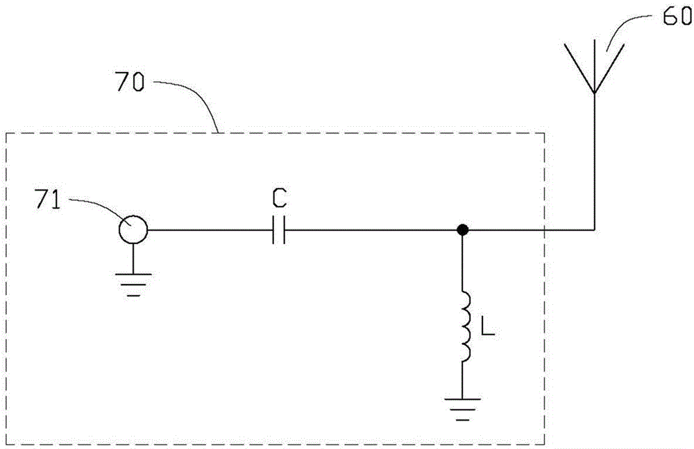
[0016] Please also refer to figure 1 and figure 2 , figure 1 Shown is a schematic plan view of a timepiece device 100 in a preferred embodiment of the present invention. In this embodiment, the clock device 100 is a portable watch, which includes a main body 10 , a dial 20 , a strap 30 , a pointer 50 , an antenna structure 60 and a matching circuit 70 .

[0017] The main body 10 is substantially circular, and its two opposite ends are connected with the strap 30 . One end of the strap 30 is provided with a buckle 40 for connecting the other end of the strap 30 . The main body 10 is used to assemble the dial 20, and the center of the dial 20 is provided with a rotating shaft 21 perpendicular thereto. The rotating shaft 21 is made of conductive material and is used to install the pointer 50 and the antenna structure 60. A part of the main body 10 A button 11 is also arranged on the side, and the button 11 is used to manually adjust the clock device 100 , for example, to cal...


PUM


Abstract

A wearable device includes a dial extending a shaft; two watch hand elements coupled to the shaft and configured to rotate 360 degrees in a plane about the shaft; an antenna element coupled to the shaft and configured to rotate 360 degrees in the same plane about the shaft; and a matching circuit matching with the antenna element.

Description

technical field [0001] The invention relates to the field of wireless communication, in particular to an antenna structure and a watch device with the antenna structure. Background technique [0002] In recent years, with the vigorous development of wireless communication technology, there has been an upsurge in the research, development and production of clock devices with wireless communication functions in the field of consumer electronics. As a component used to transmit and receive radio waves to transmit and exchange wireless data, the consideration of its performance is particularly important in the design of clock devices. The antennas of traditional timepieces are mostly designed on the strap, or in the gap around the dial close to the main body. However, when the watch device uses a metal body or a strap, the radiation performance of the antenna will inevitably be affected by the metal shielding effect. At the same time, the antenna is designed at the strap positi...

Claims


Application Information

Patent Timeline
Patent Type & Authority Applications(China)
IPC IPC(8): H01Q1/44H01Q1/22G04R20/00
CPCG04R60/06G04R60/02G04R60/14G04G21/04
Inventor 刘耿宏林彦辉
Owner SHENZHEN FUTAIHONG PRECISION IND CO LTD
Learn More