Check patentability & draft patents in minutes with Patsnap Eureka AI!

Wake-up management circuit and related wake-up method for switching converters

A technology for managing circuits and converters, applied in the wake-up field, and can solve problems such as output voltage ripple, acoustic noise, high ripple, etc.

Active Publication Date: 2018-05-11
STMICROELECTRONICS SRL
View PDF4 Cites 0 Cited by
  • Summary
  • Abstract
  • Description
  • Claims
  • Application Information

AI Technical Summary

Problems solved by technology

This causes two problems: acoustic noise due to excessive current on the transformer; and uncontrolled ripple of the output voltage due to delay in wake-up and response of the control circuit
This causes a long time high power phase of the output voltage and a higher ripple

Method used


Image

  • Wake-up management circuit and related wake-up method for switching converters
  • Wake-up management circuit and related wake-up method for switching converters
  • Wake-up management circuit and related wake-up method for switching converters

Examples


Embodiment Construction

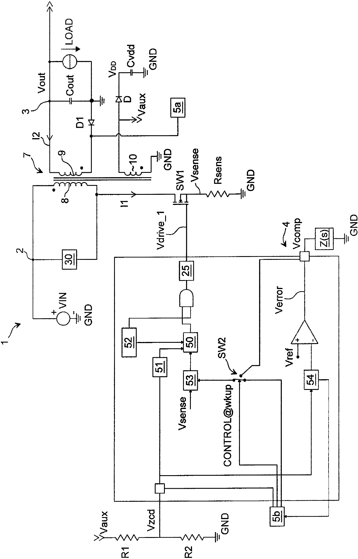
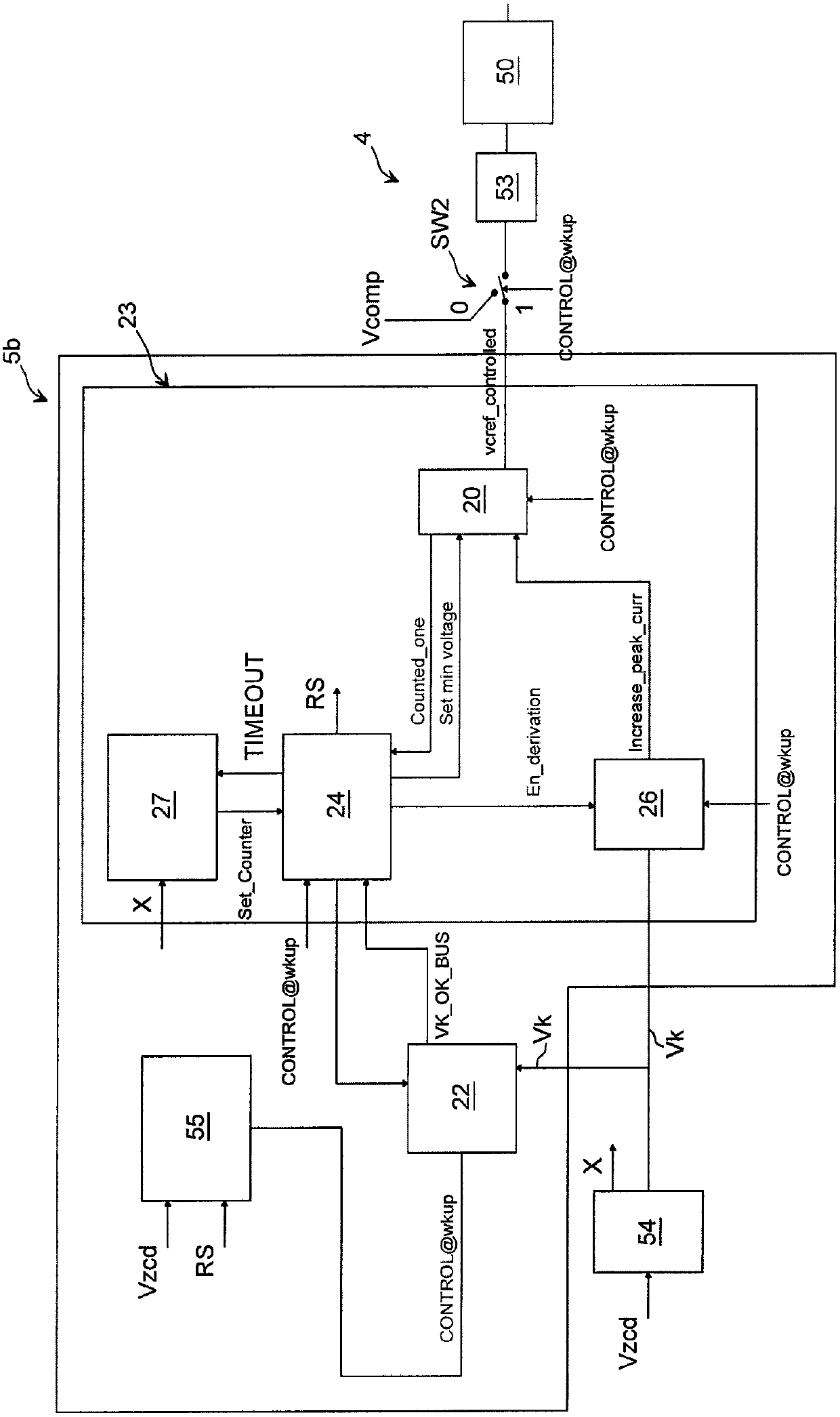
[0024] figure 1 A wake-up management circuit 5 for a switching converter 1 , preferably a DC-DC switching converter, according to the present disclosure is illustrated. The switching converter 1 comprises an input terminal 2 configured to receive an input signal Vin and an output terminal 3 configured to provide a regulated output signal Vout for powering a load LOAD. For example, the input signal Vin is a rectified mains voltage (220V).

[0025] The power converter 1 then comprises a switch SW1 coupled to the input terminal 2 and a control circuit 4 configured to drive said switch SW1 for regulating the input signal Vin and providing regulated output signals Iout, Vout at the output terminal 3 . More particularly, the switch SW1 is a power Mosfet (Metal Oxide Semiconductor Field Effect Transistor), wherein its drain terminal is coupled to the input terminal 2, its source terminal is connected to the sense resistor Rsens and its gate terminal is connected to the control cir...


PUM


Abstract

The present disclosure relates to wake-up management circuits and related wake-up methods for switching converters. A switching converter converts an input signal into a regulated output signal using a switch and a transformer with a primary winding and a primary winding. A wake-up management circuit receives the transformer demagnetization signal and is forced on by a wake-up pulse when the switching converter is operating in burst mode. Receive the sampled value of the transformer demagnetization signal. The setting circuit sets the first peak value of the current of the primary winding. A comparison circuit compares the sampled value to a voltage threshold and a previous sampled value. In response thereto, either the first peak value of the primary winding current is maintained or a new peak value is set.

Description

[0001] priority claim [0002] This application claims priority from Italian Patent Application No. MI2014A000799 filed April 30, 2014, the disclosure of which is hereby incorporated by reference. technical field [0003] The present disclosure relates to wake-up management circuits for switching converters, particularly DC-DC switching converters, and related wake-up methods. Background technique [0004] The present disclosure relates to a power switching converter that supplies a constant current to a load, such as a battery, with high efficiency. The present invention relates more particularly to switching voltage and current regulators, the load of which should be isolated from the power supply of the regulator, usually a 220V power supply. [0005] For example, a conventional power switching converter is a flyback converter in which a transformer having a primary winding and a secondary winding is provided for isolating the load from the voltage source. The primary ...

Claims


Application Information

Patent Timeline
Patent Type & Authority Patents(China)
IPC IPC(8): H02M3/335H02M1/44H02M1/14H02M1/08
CPCH02M3/33523Y02B70/10H02M1/0035H02M1/36H02M3/33515H02M1/0009H02M1/08H02M3/33507
Inventor A·帕斯夸S·图米纳罗A·拉皮萨达
Owner STMICROELECTRONICS SRL
Features
  • R&D
  • Intellectual Property
  • Life Sciences
  • Materials
  • Tech Scout
  • Unparalleled Data Quality
  • Higher Quality Content
  • 60% Fewer Hallucinations
Learn More