Three-level inverter

A technology of three-level inverters and inductors, which is applied to electrical components, AC power input to DC power output, and output power conversion devices, etc. It can solve problems such as aging damage of switches, unfavorable long-term stable operation of equipment, and bias currents. , to achieve stable performance, conducive to long-term stable operation, and easy to achieve

Inactive Publication Date: 2015-11-04
YANTAI DONGFANG WISDOM ELECTRIC +1
View PDF3 Cites 0 Cited by
  • Summary
  • Abstract
  • Description
  • Claims
  • Application Information

AI Technical Summary

Problems solved by technology

However, in practical applications, due to the deviation of the production process, the parameters of the switch modules will not be exactly the same. When the switch modules are directly connected in parallel, a bias current phenomenon will occur, which will cause the switch with a large current to age first. damage, which is not conducive to the long-term stable operation of the equipment

Method used


Image

  • Three-level inverter
  • Three-level inverter
  • Three-level inverter

Examples


Embodiment 1

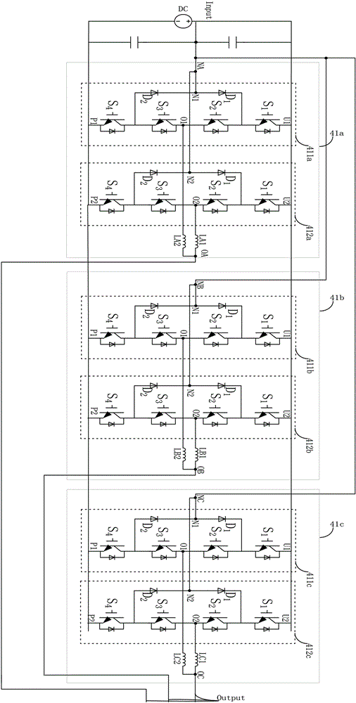
[0014] Embodiment 1: The inductor L is connected in series with the current output terminal O.

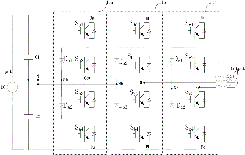
[0015] The three-level inverter in this embodiment includes an A-phase high-power switch 41a, a B-phase high-power switch 41b and a C-phase high-power switch 41c connected in parallel.

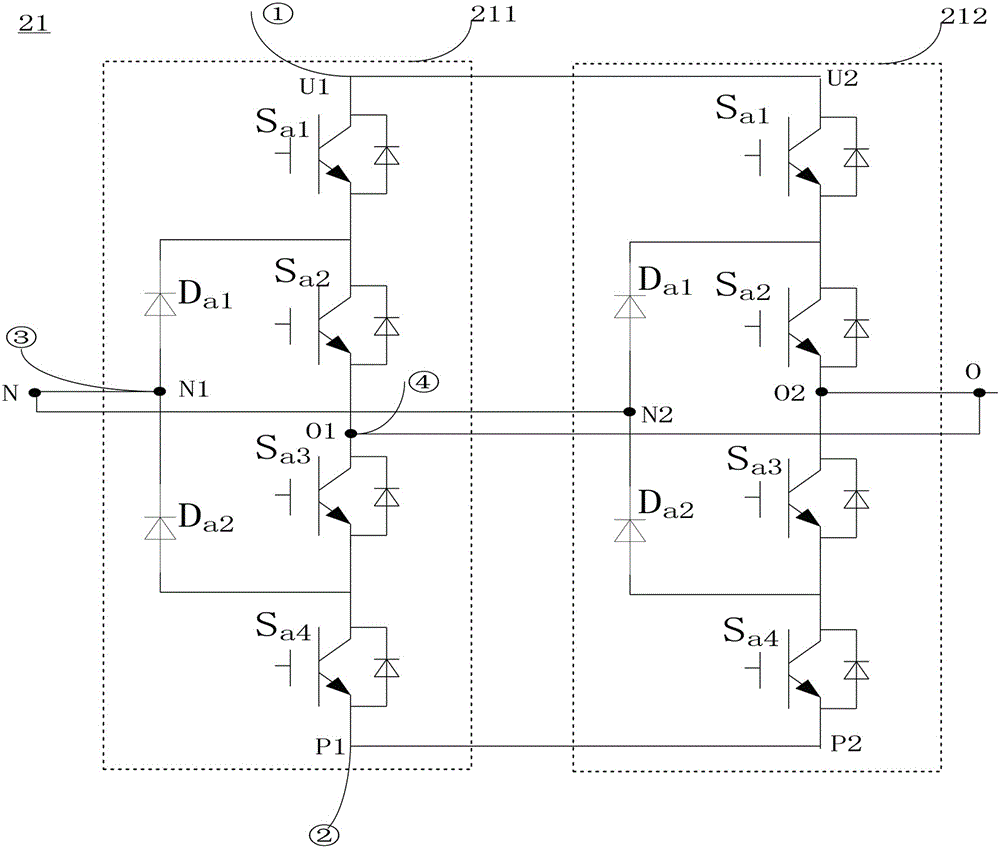
[0016] The phase A high-power switch 41a is composed of a phase A first switch module 411a and a phase A second switch module 412a connected in parallel. The B-phase high-power switch 41b is composed of a B-phase first switch module 411b and a B-phase second switch module 412b connected in parallel. The C-phase high-power switch 41c is composed of a C-phase first switch module 411c and a C-phase second switch module 412c connected in parallel.

[0017] Each switching module includes IGBT switches S connected in series 1 , IGBT switch S 2 , IGBT switch S 3 and IGBT switch S 4 . Each switch module further includes a diode D1 and a diode D2 connected in series, and the first terminal of the seri...

Embodiment 2

[0020] Embodiment 2, the inductor L is connected in series with the current input terminal N.

[0021] The intermediate terminals of the series branches of the diode D1 and the diode D2 in each switch module are used as current input terminals, each of which is connected in series with an inductor, and then connected to the input terminal of the three-level inverter. The intermediate terminals of the IGBT switch series branches in each switch module are connected to the output terminals of the three-level inverter as current output terminals. Others are the same as embodiment one.

[0022] In the above embodiments, the parameters of the inductors used by the same high-power switch are the same, so as to ensure that the output filter inductor of each phase of the three-level inverter is divided into two inductors, which are respectively arranged in the parallel high-power switch middle.


PUM


Abstract

Provided in the invention is a three-level inverter comprising an A-phase high-power switch, a B-phase high-power switch, and a C-phase high-power switch. The high-power switches are connected in parallel. The A-phase high-power switch is formed by parallel connection of an A-phase first switch module and an A-phase second switch module; the B-phase high-power switch is formed by parallel connection of a B-phase first switch module and a B-phase second switch module; and the C-phase high-power switch is formed by parallel connection of a C-phase first switch module and a C-phase second switch module. Each switch module contains a current input terminal and a current output terminal; and one of the current input terminal and the current output terminal is connected in series with an inductor and then is connected in parallel. With the inductors, precise current equalization of each module is realized and the bias current phenomenon can be effectively avoided. The three-level inverter also has outstanding characteristics of simple structure, easy realization, and stable performance.

Description

technical field [0001] The invention relates to a three-level inverter. Background technique [0002] Such as figure 1 What is shown is a three-level inverter as the prior art, and the three-level inverter inverts the direct current DC at the input terminal Input into alternating current AC and outputs it at the output terminal Output. The inverter is composed of three identical switch modules 11a / 11b / 11c, each switch module includes four IGBT switches and two diodes, and has four terminals, respectively U / N / O / P. In the inverter, when the current ia, ib or ic flowing through the switch is greater than the current rating of the switching device S, it is necessary to select a switching device with a larger current rating. [0003] Another approach in the prior art is to connect switches in parallel, and the switches connected in parallel can withstand greater current stress. Such as figure 2 As shown, switch module 211 and switch module 212 are connected in parall...

Claims


Application Information

Patent Timeline
Patent Type & Authority Applications(China)
IPC IPC(8): H02M7/537
Inventor 谢建国曼苏乐赵永胜段文勇张加庆周磊陈晨张恒彬林凯王传芬
Owner YANTAI DONGFANG WISDOM ELECTRIC
Why Eureka
Try Eureka