a catalytic reactor

A catalytic reactor and catalytic reaction technology, applied in chemical instruments and methods, chemical/physical processes, etc., can solve the problems of low usage of catalyst active components, low conversion rate of raw materials, low bed temperature, etc. Conversion rate, uniform bed temperature, and effect of reducing bed temperature

Active Publication Date: 2020-04-03
SINOPEC ENG +1
View PDF14 Cites 0 Cited by
  • Summary
  • Abstract
  • Description
  • Claims
  • Application Information

AI Technical Summary

Problems solved by technology

[0005] The purpose of this invention is to provide a kind of catalytic reactor, this catalytic reactor can solve the technical problems such as large bed pressure drop, low raw material conversion rate and easy deactivation of the bed that exist when the existing reactor is used for exothermic reaction, The catalytic reactor uses less catalyst active components, lower pressure, lower bed temperature and no "flying temperature" phenomenon

Method used


Image

  • a catalytic reactor
  • a catalytic reactor
  • a catalytic reactor

Examples


Embodiment 1

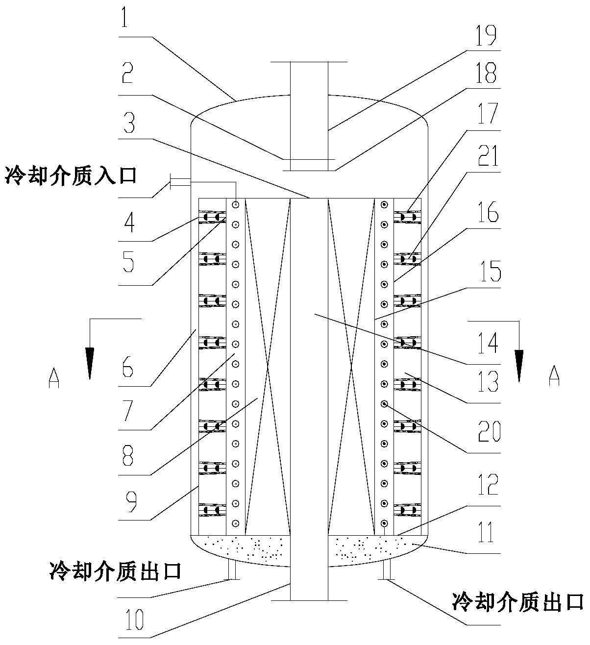
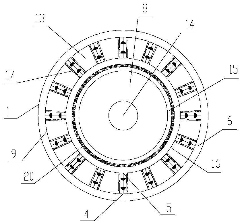
[0075] like figure 1 As shown, the catalytic reactor used in this embodiment includes a pressure housing 1 with a first straight pipe 19 at the upper end and a second straight pipe 10 at the lower end. The upper part of the first straight pipe 19 is provided with an air inlet The lower part is provided with a first gas distributor 2, and the lower part of the first gas distributor 2 is provided with a second gas distributor 18. The sleeve 13 made of microchannels arranged below the first straight pipe 19 in the housing 1 is filled with the central cylinder 8 of catalyst. The sleeve 13 shares the bottom sealing plate 12 and the top sealing plate 3 with the central cylinder 8 . All are hollow in the sleeve 13, as figure 2 shown. The sleeve 13 is provided with 99094 micro-reaction channels 17 (not all shown for clarity) arranged radially. The structure of the micro reaction channel 17, such as Figure 11 As shown, the two ends are sealingly connected with the sleeve inner w...

Embodiment 2

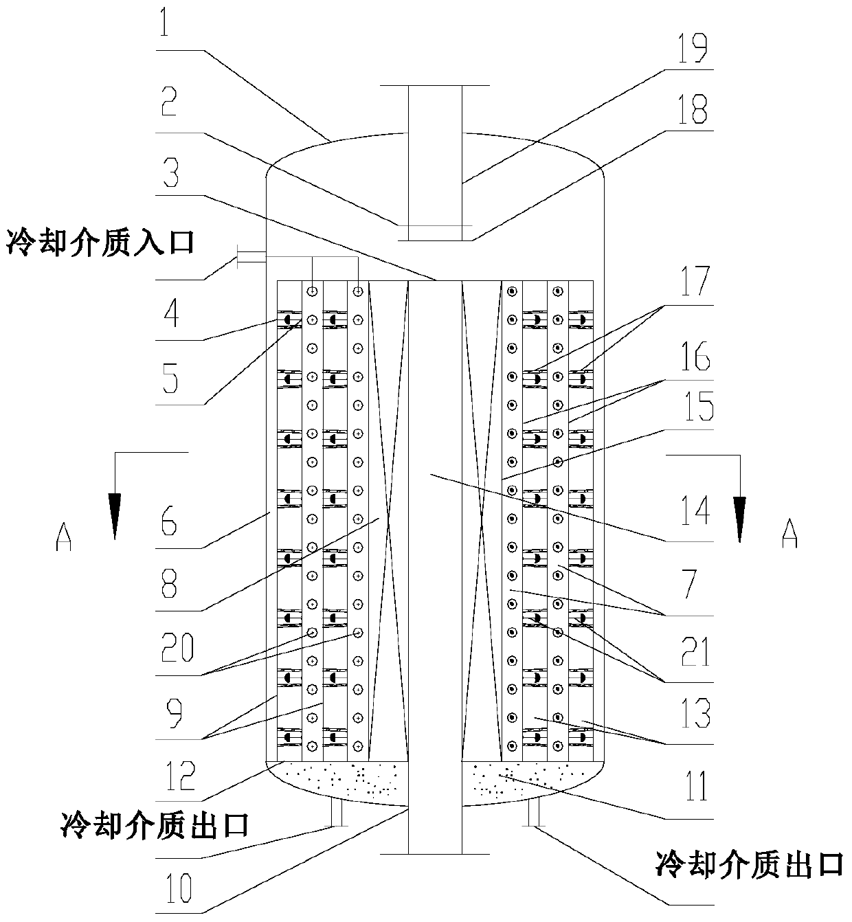
[0082] like image 3 , Figure 4 As shown, the catalytic reactor used in this embodiment has the same structural parameters as the catalytic reactor housing inner diameter and central cylinder of the first embodiment. The difference from Embodiment 1 is that in this embodiment, two sleeves are used, and cooling medium pipelines are arranged between the sleeves and between the sleeve and the central cylinder, the ring gap distance is still 30mm, and the gap distance is 10mm , the diameter of the central tube 14 is 150mm, the radial bed thickness of the central tube 8 is 175mm, the length of the micro-reaction channel of the tapered tube is 75mm, the diameter of the inlet of the tapered tube is 8mm, and the diameter of the outlet is 4mm. The total volume of all the tapered tubes accounts for The volume ratio of the sleeve 13 is 48.6%. The diameter of the bottom surface of the hemisphere of the flow guide element is 3mm, and the distance between adjacent flow guide elements is ...

Embodiment 3

[0085] like Figure 5 , Image 6 As shown, the catalytic reactor used in this embodiment has the same structural parameters as the catalytic reactor housing inner diameter, center tube, and sleeve in Example 1. The difference from Embodiment 1 is that no cooling medium pipeline is used in this implementation, and the cooling medium enters the casing 1 from the cooling medium inlet on the outside of the casing 1, and the cooling medium inlet is connected with the sleeve through the cooling medium pipeline. The inner wall of 13 is in fluid communication with the chamber formed by the outer wall of the micro-reaction channel 17, and the chamber is in fluid communication with the cooling medium outlet through two cooling medium pipelines passing through the heat insulating material area 11, and the cooling medium is sent out reactor.

[0086] The catalytic reactor used in this example can be applied to syngas synthesis of C in Fe-based catalysts 2 = 、C 3 = and other small mo...


PUM


Abstract

The invention discloses a catalytic reactor. The reactor includes a cylindrical sealed pressure-bearing housing (1), a first straight tube (19) extending from the top of the housing (1) to the insideof the housing, a second straight tube (10) extending from the bottom of the housing (1) to the inside of the housing, and a catalytic reaction unit arranged inside the housing (1), below the first straight tube (19), and above the second straight tube (10). Compared with a catalytic reactor in the prior art, the catalytic reactor is compact in structure, less in active metal consumption, high intarget product selectivity, small in bed pressure drop, and low in temperature, and the phenomenon of temperature runaway isn't taken place in the bed.

Description

technical field [0001] The invention relates to the field of chemical machinery, in particular to a catalytic reactor. Background technique [0002] Fixed bed reactors mainly include axial fixed bed reactors and radial fixed bed reactors. The axial fixed bed reactor is relatively easy to design and process, and simple to operate, but there are problems such as large reactor equipment size, large bed pressure drop, prone to local temperature jump, slow heat transfer, low conversion rate, and obvious amplification effect. The radial bed reactor has a large height-to-diameter ratio, a small bed pressure drop, and a short residence time of the reactants in the catalyst bed, but it is difficult to achieve uniform distribution of the reactants in the radial direction, and the production intensity of the unit catalyst bed is low. [0003] In order to overcome the problems of low heat transfer and mass transfer efficiency in traditional chemical industry, microchemical technology e...

Claims


Application Information

Patent Timeline
Patent Type & Authority Patents(China)
IPC IPC(8): B01J8/02
Inventor 张旭戴文松蒋荣兴
Owner SINOPEC ENG
Why Eureka
Try Eureka