Multi-triggering source low-power dissipation self-locking electronic switch

An electronic switch and trigger source technology, applied in electronic switches, electrical components, pulse technology, etc., can solve the problems of suspended test, small size, and inability to provide mechanical power switches in the internal recorder.

Inactive Publication Date: 2015-11-04
710TH RES INST OF CHINA SHIPBUILDING IND CORP
View PDF6 Cites 2 Cited by
  • Summary
  • Abstract
  • Description
  • Claims
  • Application Information

AI Technical Summary

Problems solved by technology

[0003] This type of product is small in size and cannot provide a mechanical power switch for the internal recorder, and the product may be stored for a long time fro

Method used


Image

  • Multi-triggering source low-power dissipation self-locking electronic switch

Examples


Embodiment Construction

[0017] The present invention will be described in detail below with reference to the accompanying drawings and examples.

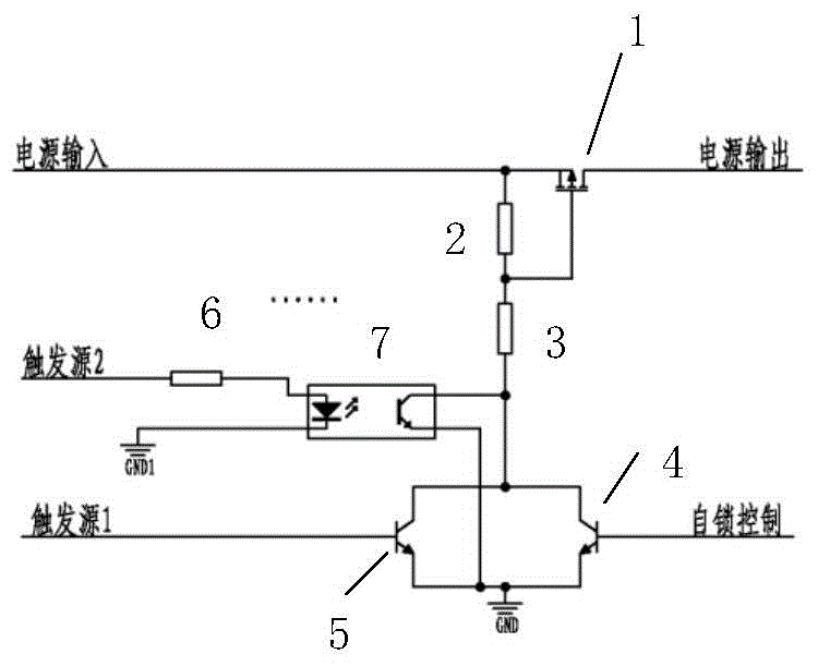
[0018] like figure 1 As shown, the present invention adopts multiple trigger sources to realize the power supply control to the electrical equipment, and the electronic switch is composed of a MOS tube 1, a first resistor 2, a second resistor 3, a self-locking control transistor 4, and a first type trigger source connection circuit and the second type of trigger source connection circuit.

[0019] The first type trigger source connection circuit is only composed of a triode 5, the base of the triode is used as the input end of the first type trigger source connection circuit, the collector is used as the output end of the first type trigger source connection circuit, and the emitter is used as the first Connect the trigger source to the ground terminal of the circuit.

[0020] The second type trigger source connection circuit consists of a trigger source...


PUM


Abstract

The invention discloses a multi-triggering source low-power dissipation self-locking electronic switch, and uses multiple triggering sources to realize power supply control of electric equipment. The electronic switch comprises a first-category triggering source junction circuit formed by a triode and a second-category triggering source junction circuit formed by a triggering source resistor and an optical coupler; if being common-grounded, the triggering sources and the electric equipment are accessed to the first-category circuit; if being not common-grounded, the triggering sources and the electric equipment are accessed to the second-category circuit; a source electrode of a MOS transistor is connected to a collector electrode of a self-locking control triode, a grid electrode of the MOS transistor is connected to the collector electrode of the self-locking control triode through a resistor, and an output end of the first-category circuit and an output end of the second-category circuit are connected to the collector electrode of the self-locking control triode; and both the first-category triggering source junction circuit and second-category triggering source junction circuit have grounding ends, and an emitting electrode of the self-locking control triode is connected to the ground. The circuits can realize flexible control of the multiple triggering sources and low power dissipation.

Description

technical field [0001] The invention belongs to the field of electronic switches. Background technique [0002] In the development process of a certain type of product, an internal recorder is required to record the internal signal and working status of the product. There are various test methods and processes in the development of this product, which requires the built-in power supply of the internal recorder, which can be flexibly powered on and started in various tests, and can be automatically powered off after the test is completed. [0003] This type of product is small in size and cannot provide a mechanical power switch for the internal recorder. After the product is assembled, it may be stored for a long time for several days to several months before the test. After the test starts, the test may be suspended due to various situations. Contents of the invention [0004] In view of this, the present invention provides a low-power self-locking electronic switch with...

Claims


Application Information

Patent Timeline
IPC IPC(8): H03K17/78H03K17/687
Inventor 王国博王绪军邓秀华
Owner 710TH RES INST OF CHINA SHIPBUILDING IND CORP
Why Eureka
Try Eureka