
Pressure-type rice cooker

A rice cooker and pressure technology, applied in pressure cookers, cooking utensils, household utensils, etc., can solve problems such as difficulties and differences in adjustment accuracy

Active Publication Date: 2015-11-11
PANASONIC INTELLECTUAL PROPERTY MANAGEMENT CO LTD
View PDF8 Cites 13 Cited by
  • Summary
  • Abstract
  • Description
  • Claims
  • Application Information

AI Technical Summary

Problems solved by technology

Therefore, it becomes more difficult to adjust the pressure in the pot to a predetermined value higher than the atmospheric pressure, and the adjustment accuracy varies from one rice cooker to another.

Method used


Image

  • Pressure-type rice cooker
  • Pressure-type rice cooker
  • Pressure-type rice cooker

Examples


Embodiment approach 1

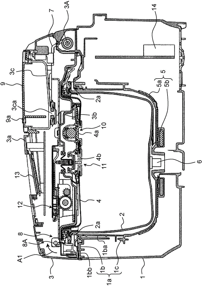
[0055] use figure 1 , the overall structure of the pressure rice cooker according to Embodiment 1 of the present invention will be described. figure 1 It is a schematic cross-sectional view of the pressure rice cooker of this embodiment.

[0056] Such as figure 1 As shown, the pressure rice cooker of this embodiment is provided with: a substantially bottomed cylindrical rice cooker main body 1 having a pot storage portion 1a formed therein; Add to cooked food including rice and water.

[0057] An openable and closable hollow lid 3 is attached to the upper opening of the rice cooker main body 1 . A substantially disk-shaped inner lid 4 capable of sealing the upper opening of the pot 2 is detachably attached to the inside of the lid 3 (the side covering the upper opening of the pot 2 ). In the present embodiment, an openable and closable lid provided on the upper opening of the pot 2 is constituted by the lid 3 and the inner lid 4 .

[0058] The pot storage part 1a of the r...

Embodiment approach 2

[0141] Next, the structure of the pressure type rice cooker concerning Embodiment 2 of this invention is demonstrated. This embodiment includes an inner cover 24 and a pressure reducing valve moving mechanism 52 , and the inner cover 24 and the pressure reducing valve moving mechanism 52 have structures different from those of the inner cover 4 and the pressure reducing valve moving mechanism 52 in the first embodiment. In this embodiment, the same or corresponding parts as those in Embodiment 1 are given the same reference numerals, and descriptions thereof are omitted.

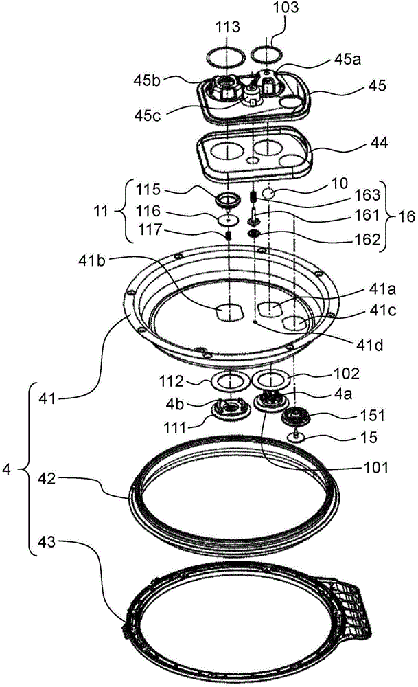
[0142] Figure 11 It is an exploded perspective view of members related to the inner cover 24 in this embodiment. Figure 12 is only magnified by Figure 11 An exploded perspective view of the part enclosed by the dotted line in .

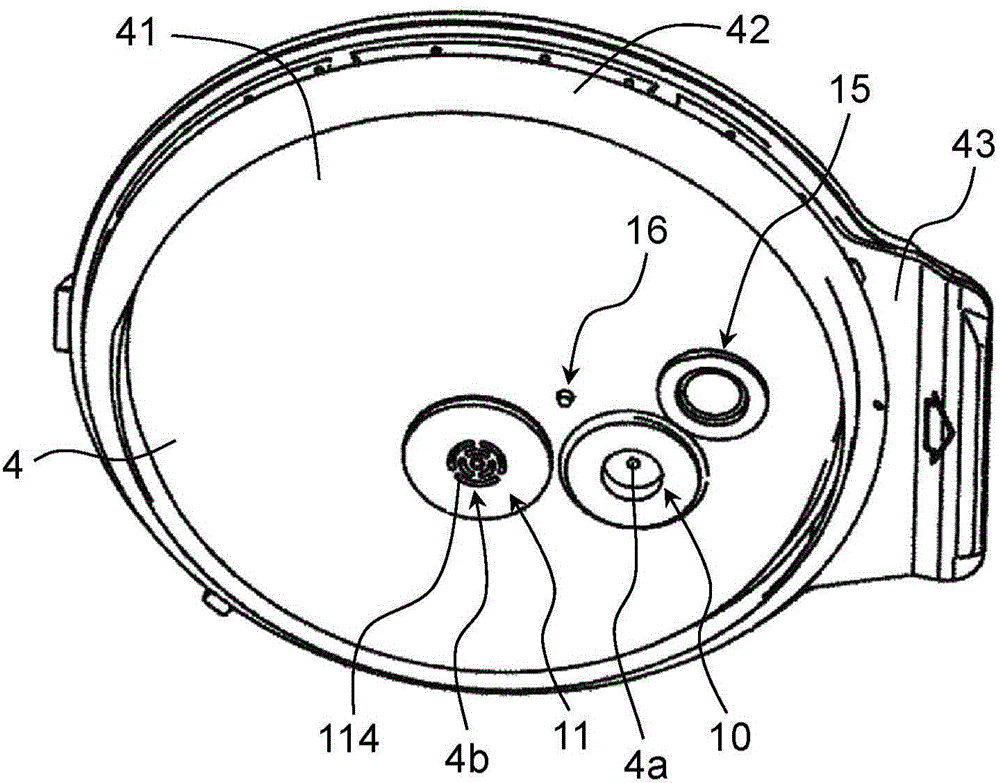
[0143] Figure 13 It is a perspective view of the member related to the inner lid 24 in this embodiment seen from the bottom surface side (pot 2 side) of the inner lid 24. ...


PUM


Abstract

The present invention provides a pressure-type rice cooker. A pressure control valve (10) may be configured to be a first vapour discharge hole (4a) which is capable of opening and closing and is arranged at a cover body. A reducing valve (11) may be configured to a second vapour discharge hole (4b), arranged at the cover body, upwards elastically applied by power, moved along the thickness direction of the cover body and being capable of opening and closing. A reducing valve travel mechanism (12) comprises a reducing valve drive rod disposed within the cover body and moved along the direction vertical to the thickness direction of the cover direction; and an inclined surface configured to move along the thickness direction of the cover body in a movement link of the reducing valve drive rod mode via the inclined surface. The reducing valve is moved along the thickness direction of the cover body in a movement link of the reducing valve drive rod mode. According to the structure, openings of the vapour discharge hole may be enlarged while the large scale of the rice cooker is restrained, and the pressure in a pot may be more accurately adjusted to the specified value higher than the barometric pressure.

Description

technical field [0001] The present invention relates to a pressure-type rice cooker configured to stir rice grains in a pot by decompressing the pressure in the pot to cause water in the pot to boil. Background technique [0002] In the past, as such a pressure type rice cooker, for example, pressure type rice cookers described in Patent Document 1 (Japanese Unexamined Patent Application Publication No. 2004-81824) and Patent Document 2 (Japanese Patent Application Publication No. 2004-57556) are known. . [0003] Patent Document 1 discloses a pressure-type rice cooker including a ball that covers a steam discharge hole provided on a lid by its own weight, and moves the ball forcibly to open the steam discharge hole. The hole solenoid (Solenoid) drives the solenoid to open the steam discharge hole in the boiling maintenance process. [0004] According to the pressure rice cooker of Patent Document 1, the steam discharge hole is opened in the boiling maintaining step, where...

Claims


Application Information

Patent Timeline
IPC IPC(8): A47J27/086A47J27/09
Inventor 大矢弘水谷幸二郎后藤隆博北木宏冈本大辅山地宏和
Owner PANASONIC INTELLECTUAL PROPERTY MANAGEMENT CO LTD
Learn More