Magnetic navigation pedicle screw

A pedicle screw and magnetic technology, applied in the field of medical devices, can solve the problems of loss of intervertebral disc height, excessive displacement of the pedicle screw, surgical failure and complications, and achieve the effect of improving the success rate of surgery and improving the quality of surgery

Active Publication Date: 2015-11-11
浙江德康医疗器械有限公司
View PDF5 Cites 1 Cited by
  • Summary
  • Abstract
  • Description
  • Claims
  • Application Information

AI Technical Summary

Problems solved by technology

[0003] In the screw-rod internal fixation system, the accurate implantation of the pedicle screw during the operation plays a key role in the success of the operation, and the traditional operation relies on the doctor's feel and experience; and the postoperative load of the pedicle screw is too large, and the screw position is improper. Intervertebral disc degeneration causes loss of intervertebral disc height, osteoporosis or insufficient postoperative recovery time and other factors cause excessive displacement or even fracture of pedicle screws in the body, resulting in surgical failure and complications

Method used


Image

  • Magnetic navigation pedicle screw
  • Magnetic navigation pedicle screw
  • Magnetic navigation pedicle screw

Examples


Embodiment 1

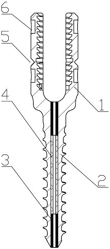
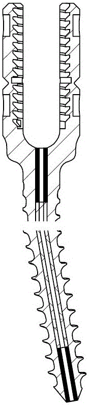
[0029] Embodiment 1: The threaded screw rod 2 and the U-shaped nail wall 1 are integrally formed.

[0030] The through hole extends to the bottom of the U-shaped nail wall along the axis of the screw shank.

Embodiment 2

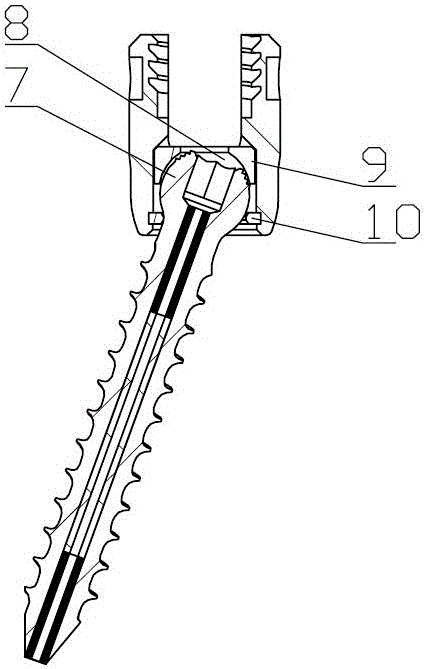
[0031] Embodiment 2: the rear end of the threaded screw rod 2 is provided with a spherical acetabular body 7, the bottom of the U-shaped nail wall 1 is provided with an acetabular cup 8 that is compatible with the acetabular body 7, and the acetabular body 7 is accommodated in The acetabular cup 8 and the two are slidably matched, and the front end of the acetabular cup 8 is provided with a limiting part for limiting the threaded screw rod 2 .

[0032] The limiting part includes a collar 10 and a retaining ring 9 . The retaining ring is set in the acetabular cup of the U-shaped nail wall, and then the acetabular body is placed in the retaining ring, the retaining ring limits the upward movement of the acetabular body, and the collar clamps the acetabular body in the acetabular cup, and the retaining ring limits acetabular dislodgement cup

[0033] The outer surface of the U-shaped nail wall is provided with a blind hole 6, and the purpose of setting the blind hole 6 is to ass...

Embodiment 3

[0034] Embodiment 3, a notch 5 is provided on the outer surface of the U-shaped nail wall 1. The purpose of setting the notch 5 is to facilitate the breaking of the U-shaped nail wall and take the broken part out of the body after the operation is completed.


PUM


Abstract

The invention provides a magnetic navigation pedicle screw. The magnetic navigation pedicle screw comprises a threaded screw rod and a U-shaped screw wall which are integrally formed. An internal thread is formed in the inner wall of the U-shaped screw wall. A through hole along the axis of the threaded screw rod is formed in the threaded screw rod. Magnetic materials are arranged at the upper end and the lower end of the through hole. A partition piece is arranged between the magnetic materials at the upper end and the lower end. A magnetic material is arranged in the threaded screw rod. The magnetic navigation pedicle screw is used in cooperation with a magnetic sensor for positioning and monitoring the screw entering position, angle and depth and other data in surgery, and therefore the problem that traditional surgery relies on experience, hand feeling and the like of doctors is solved, the surgery success rate and surgery quality are increased, and the requirement of minimally invasive surgery is met; in addition, whether screw breakage happens during screw entering in surgery or not can be judged according to the magnetic materials in a screw body, whether the screw body is broken or not and whether abnormal displacement happens between pedicle screws or not can be found in time through the magnetic navigation pedicle screw in cooperation with an in-vitro monitoring device in the postmastectomy relief period, and a patient is helped to go to a doctor in time.

Description

technical field [0001] The invention belongs to the technical field of medical devices, and mainly relates to a magnetic navigation pedicle screw. Background technique [0002] The application of spinal internal fixation technology has a history of several decades. The traditional screw-rod internal fixation system generally consists of pedicle screws, orthopedic rods, connectors, cross-links and lock nuts. Through open spinal surgery, supplemented by a screw-rod internal fixation system to fix and support the spine, correct deformities, and promote bone fusion recovery, so as to treat spinal disorders. [0003] In the screw-rod internal fixation system, the accurate implantation of the pedicle screw during the operation plays a key role in the success of the operation, and the traditional operation relies on the doctor's feel and experience; and the postoperative load of the pedicle screw is too large, and the screw position is improper. Intervertebral disc degeneration c...

Claims


Application Information

Patent Timeline
Patent Type & Authority Applications(China)
IPC IPC(8): A61B17/70
CPCA61B17/00234A61B17/7062A61B17/7076A61B2017/00876
Inventor 许小波任宏亮沈嘉桢崔明星任涛
Owner 浙江德康医疗器械有限公司
Why Eureka
Try Eureka