
Mixed liquor continuous separation device

A separation device and mixed liquid technology, applied in the field of chemical equipment, can solve problems such as narrow application range, complex structure, impact on energy saving, emission reduction and waste reuse, and achieve the effect of increasing applicability, increasing effect and speed

Active Publication Date: 2015-11-11
JIANGSU CHANGJILI NEW ENERGY TECH CO LTD
View PDF5 Cites 4 Cited by
  • Summary
  • Abstract
  • Description
  • Claims
  • Application Information

AI Technical Summary

Problems solved by technology

At present, the liquid separation devices we know are either too complicated in structure and low in energy consumption; The effect of reuse

Method used


Image

  • Mixed liquor continuous separation device
  • Mixed liquor continuous separation device
  • Mixed liquor continuous separation device

Examples


Embodiment 1

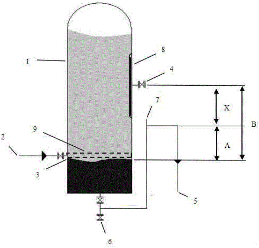
[0021] like figure 1 As shown, the device provided by the present invention comprises a mixed liquid water separation container 1, a mixed liquid inlet 2, a water separation interface 3, an organic liquid overflow port 4, an aqueous phase overflow port 5, a net discharge port 6, and a vent port 7; The interface 3 is the reference surface, the height of the organic liquid overflow port 4 is B, the height of the water phase overflow port 5 is A, and the height difference between the two is X=B-A, B*ρ 1 =A*ρ 2 , where ρ 1 is the organic phase density, ρ 2 is the density of the aqueous phase.

[0022] The device also includes a height controller 8 for the organic liquid overflow 4 .

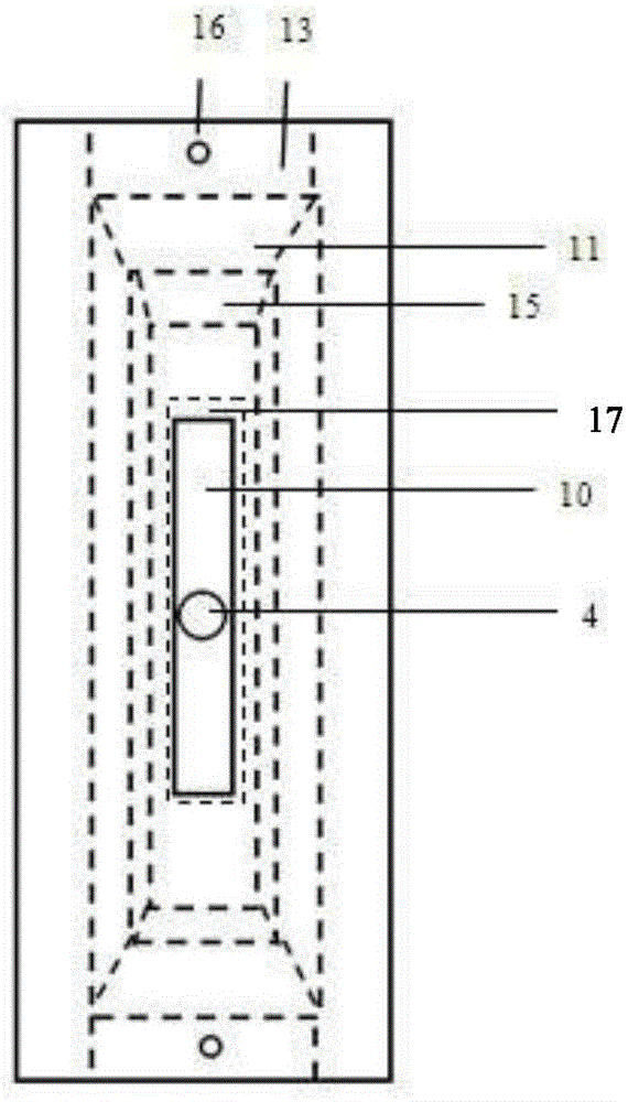
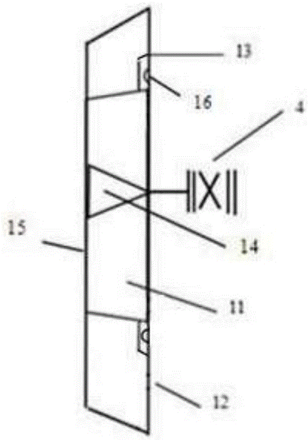
[0023] Among them, such as figure 2 and 3 The shown height controller 8 includes the outer wall 12 of the mixed liquid water separation container 1, the inner wall 15 of the mixed liquid water separation container 1, the width of the elastic piston 11 is the same as that formed by the inner an...


PUM


Abstract

The invention belongs to the technical field of chemical equipment and provides a mixed liquor continuous separation device. The device comprises a mixed liquor water diversion container (1), a mixed liquor inlet (2), a water diversion interface (3), an organic liquid overflow port (4), an aqueous phase overflow port (5), a thorough discharge port (6) and a venting port (7). With the water diversion interface (3) as the reference surface, the height of the organic liquid overflow port (4) is B, the height of the aqueous phase overflow port (5) is A, the height difference between the organic liquid overflow port (4) and the aqueous phase overflow port (5) is X=B-A, B*rho 1=A*rho 2, rho 1 represents organic phase density, and rho 2 represents aqueous phase density. By means of the density difference between two kinds of immiscible liquid, the positions of the organic liquid outflow port and the aqueous phase overflow port are reasonably designed, and automatic separation of the two kinds of immiscible liquid can be achieved through the equipment.

Description

technical field [0001] The invention belongs to the technical field of chemical equipment and relates to a continuous separation device for mixed liquid. Background technique [0002] In industrial production, two incompatible mixed liquids are often produced. If the mixed liquid is dumped directly, it will not only cause a great waste of resources, but also pollute the environment; for subsequent treatment or production, processing and reuse, it must first be dumped The two liquids are separated to be processed and utilized according to their respective properties. We know that mutually incompatible liquids have different densities, and after standing still, stratification will inevitably occur. In the prior art, the stratification phenomenon of two liquids is generally used to achieve the purpose of separation. At present, the liquid separation devices we know are either too complicated in structure and low in energy consumption; The effect of reuse. Contents of the i...

Claims


Application Information

Patent Timeline
IPC IPC(8): B01D17/02
Inventor 周卫强黄卫军史先乔谢云良陈浩
Owner JIANGSU CHANGJILI NEW ENERGY TECH CO LTD
Learn More