Method and Apparatus for Pumping Liquids Using Directional Growth and Elimination Bubbles

a technology of directional growth and elimination bubbles, which is applied in the direction of positive displacement liquid engines, machines/engines, electrochemical generators, etc., can solve the problems of difficult, if even possible, and the energy-intensive bubble-actuation method, and achieve the effect of small-scale devices

Active Publication Date: 2008-05-22
RGT UNIV OF CALIFORNIA
View PDF8 Cites 29 Cited by
  • Summary
  • Abstract
  • Description
  • Claims
  • Application Information

AI Technical Summary

Benefits of technology

[0017]It is thus one object of the invention to provide a method and apparatus for the directional growth and transport of bubbles within a fluidic environment. It is an additional embodiment of the invention to provide a means of removing bubbles entrained in a fluid flow. The bubbles are able to be removed from fluid flow without having to rely on condensation, dissolution, or diffusion. It is a further object of the invention to provide a device and method that utilizes “ephemeral” bubbles to provide a motive or pumping force to a fluid contained within a flow path. The device and method has particular applicability to small-scale devices such as microfluidic-based devices. It is still another object of the invention to provide a pumping mechanism that can be implemented in fuel cells that utilizes the gaseous byproduct(s) as a driver for a new or fresh fuel for the fuel cell. The pumping method also enables the use of insoluble gas bubbles for the liquid delivery in various microfluidic devices, so as to address the concerns of specific applications, such as energy efficiency, thermal sensitivity, bio-compatibility, or adjustable flow rate.

Problems solved by technology

Unfortunately, this bubble-actuation method is energy intensive due to the high heat loss present in the microscale environment.
Bubble elimination is also a problem.
As for other bubble generation methods, removal of insoluble gas bubbles from a sealed device is harder—if even possible at all.
This difficulty has been discouraging bubble-driven pumps from using bubble generation methods other than boiling (e.g., direct injection or electrolysis).
Currently, there is no bubble-driven pump suitable to circulate liquid in a closed-loop microfluidic device.

Method used


Image

  • Method and Apparatus for Pumping Liquids Using Directional Growth and Elimination Bubbles
  • Method and Apparatus for Pumping Liquids Using Directional Growth and Elimination Bubbles
  • Method and Apparatus for Pumping Liquids Using Directional Growth and Elimination Bubbles

Examples


Embodiment Construction

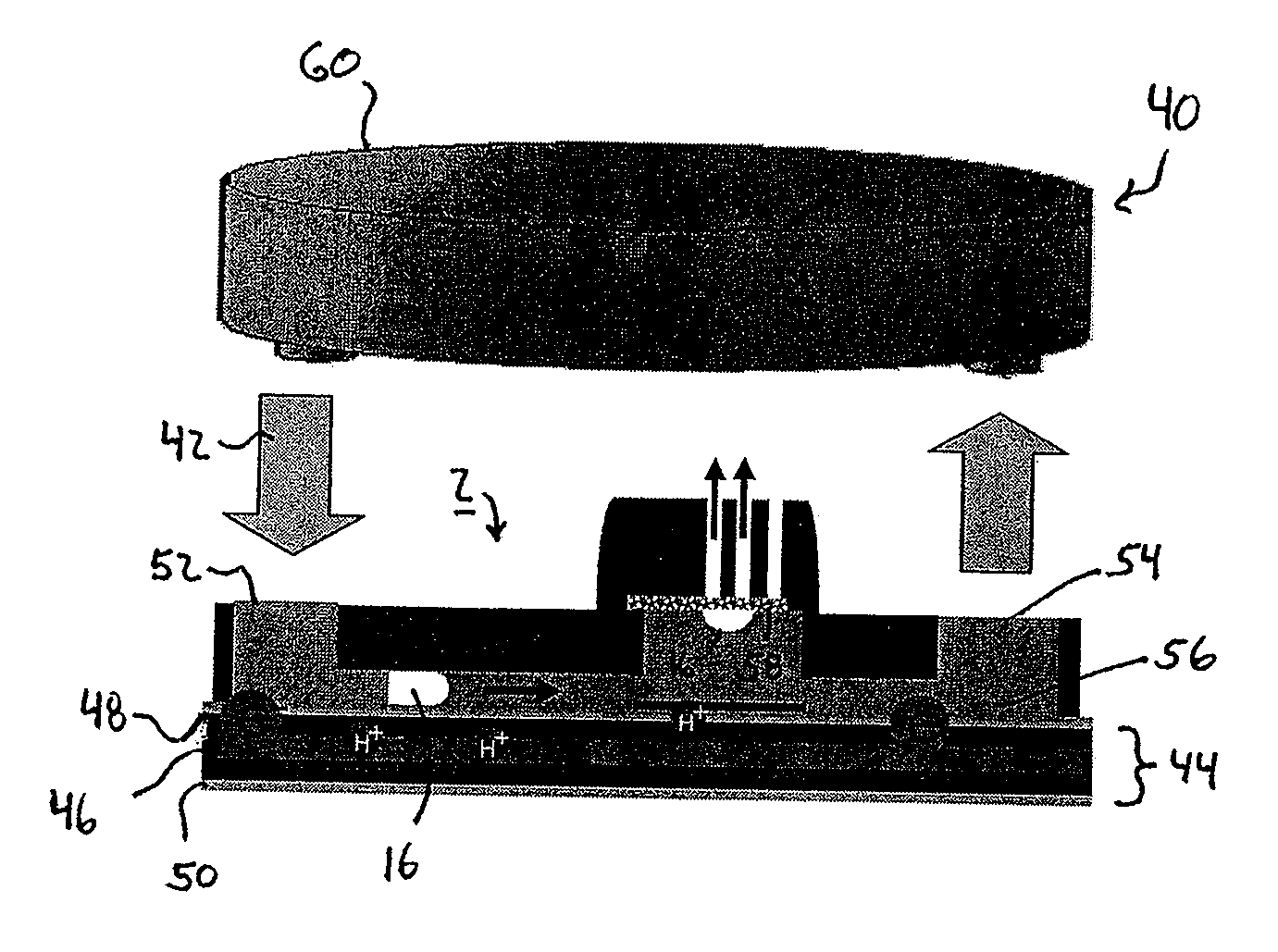
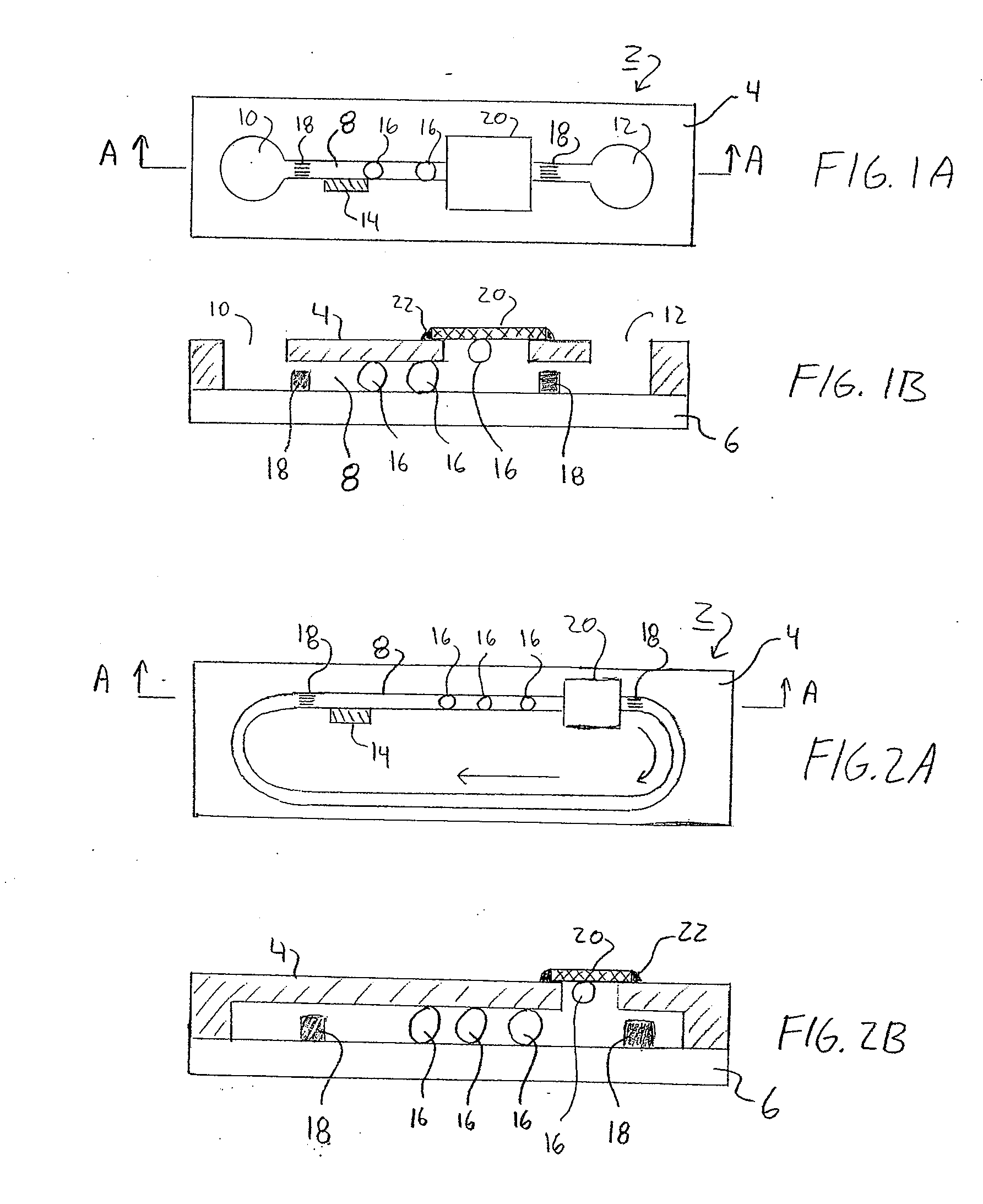
[0035]FIGS. 1A and 1B illustrates a pumping device 2 according to one embodiment of the invention. The pumping device 2 may be formed as a microfluidic-based pump 2 that is formed inside a substrate 4 which can be easily micromachined to form microchannels, e.g. silicon or PDMS (Polydimethylsiloxane). The substrate 4 is bonded or otherwise secured to secondary substrate 6 such as a glass plate or the like to close the microchannel. One or more channels 8 are formed between the first and second substrates 4, 6. The channel(s) 8 may be connected to an inlet 10 and outlet 12 as is shown in FIGS. 1A, 1B. FIGS. 1A and 1B illustrate an embodiment of a pumping device 2 in an open configuration, wherein fluid (not shown) contained within the channel 8 does not re-circulate or recycle within the device 2.

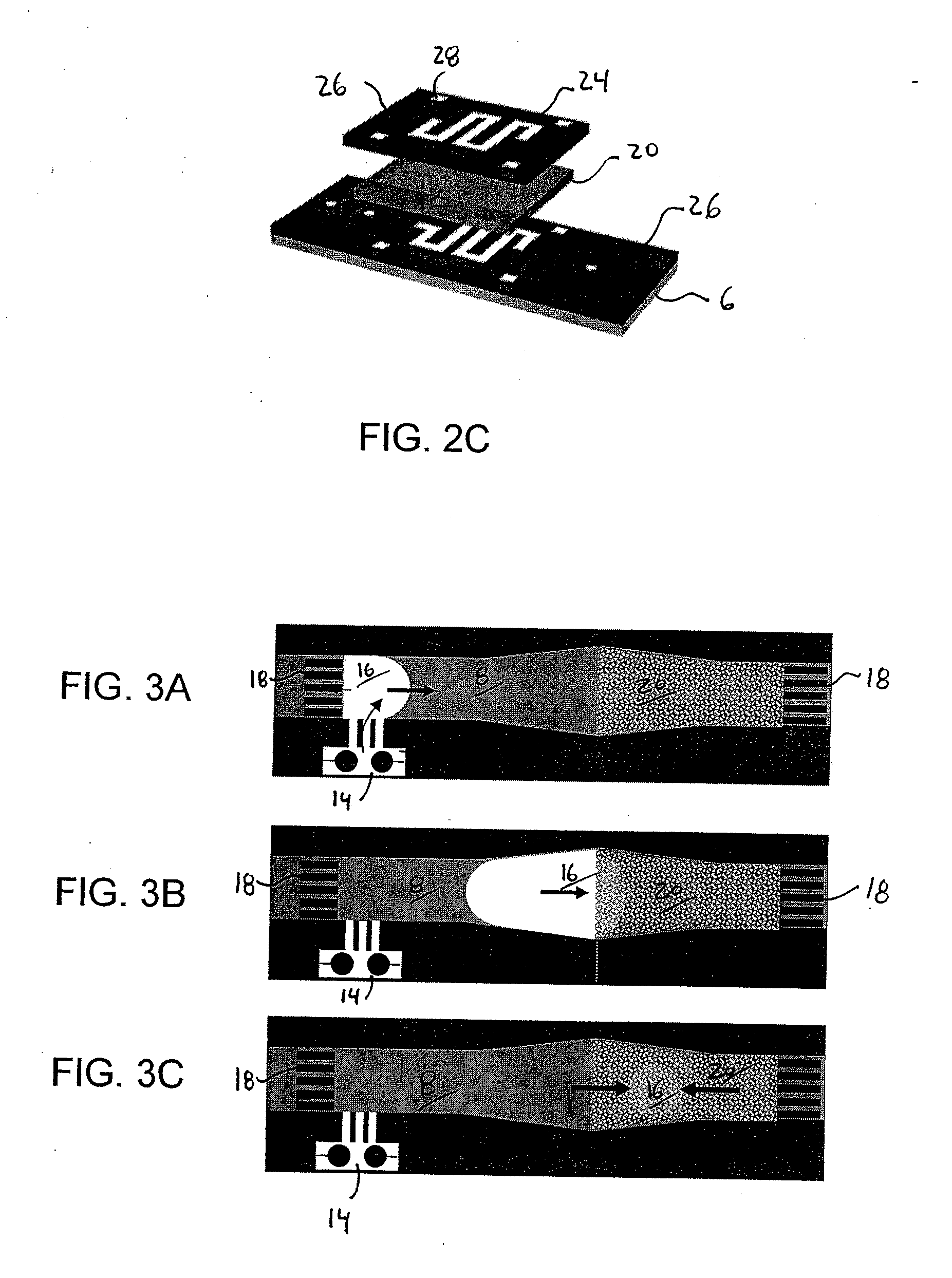
[0036]The pump device 2 includes a bubble generator 14. The bubble generator 14 is disposed at or adjacent to the channel 8 and is used to generate a plurality of individual gaseous vesicles...


PUM

PropertyMeasurementUnit
diameteraaaaaaaaaa
diameteraaaaaaaaaa
pore diameteraaaaaaaaaa

Abstract

A method and device for the pumping of liquids utilizes the directional growth and elimination of gaseous vesicles or bubbles to provide the motive or pumping force. In one embodiment, the pumping device is a microfluidic pumping mechanism having a channel, a bubble generator for generating a plurality of bubbles within the channel, and a venting membrane disposed over a portion of the channel downstream of the bubble generator. A one-way valve or directional resistance feature is positioned upstream of the bubble generator to introduce directional transport of bubbles within the channel. The method and device may be integrated into micro fuel cells with organic liquid fuel such that liberated gaseous bubbles may be utilized to deliver fresh fuel or circulate reusable fuel without any power-consuming components.

Description

REFERENCE TO RELATED APPLICATIONS[0001]This Application claims priority to U.S. Provisional Patent Application No. 60 / 647,139 filed on Jan. 25, 2005. U.S. Provisional Patent Application No. 60 / 647,139 is incorporated by reference as if set forth fully herein.STATEMENT REGARDING FEDERALLY SPONSORED RESEARCH AND DEVELOPMENT[0002]The U.S. Government may have a paid-up license in this invention and the right in limited circumstances to require the patent owner to license others on reasonable terms as provided for by the terms of Grant No. DAAH01-01-1 from the Defense Advanced Research Projects Agency (DARPA).FIELD OF THE INVENTION[0003]The field of the invention generally relates to devices used to pump or transfer liquids from one location to another. In particular, the field of the invention relates to devices and methods that utilize gaseous fluids such as bubbles to pump liquids. In one aspect of the invention, the device and method can be incorporated into fuel cells to take advant...

Claims


Application Information

Patent Timeline
Patent Type & Authority Applications(United States)
IPC IPC(8): H01M8/02F04B19/24
CPCF04B19/006F04B19/24Y02E60/523H01M8/1011H01M8/04201Y02E60/50
Inventor KIM, CHANG-JINMENG, DE-SHENG
Owner RGT UNIV OF CALIFORNIA
Why Eureka
Try Eureka