Supercharge Your Innovation With Domain-Expert AI Agents!

Drive drawing mechanism of enameling machine wire storage device

The technology of a traction mechanism and a wire storage device is applied in the directions of transportation and packaging, transportation of filamentous materials, and processing of thin materials. Effect

Inactive Publication Date: 2015-11-11
TIANJIN JINGWEI HUIKAI OPTOELECTRONICS CO LTD
View PDF0 Cites 3 Cited by
  • Summary
  • Abstract
  • Description
  • Claims
  • Application Information

AI Technical Summary

Problems solved by technology

[0004] However, in the process of producing enameled wire, it is only pulled by the traction force of the enamelling machine, and after installing the wire storage device, the distance from the wire to the enamelling machine is nearly 100 meters, and the wire may be drawn under such a pulling force. silk phenomenon
Moreover, the pay-off machine is also passive and has no power itself, which increases the wire drawing phenomenon.

Method used


Image

  • Drive drawing mechanism of enameling machine wire storage device

Examples


Embodiment Construction

[0015] Next, an active pulling mechanism of an enamelling machine wire accumulator as an example of the present invention will be described based on the drawings.

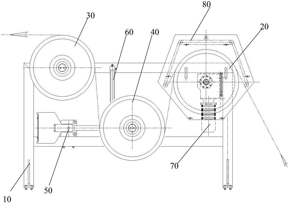
[0016] figure 1 It is an enlarged schematic diagram showing the active traction mechanism of the enamelling machine wire storage device of the present invention.

[0017] Such as figure 1 As shown, the active traction mechanism of the wire storage device of the enamelling machine of the present invention has a frame body 10 , a traction wheel 20 , an output wheel 30 , a traction control wheel 40 , a rotary encoder 50 and a damping cylinder 60 .

[0018] The traction wheel 20 and the output wheel 30 are installed at both ends of the frame body 10 , and the traction control wheel 40 is installed on the frame body 10 between the traction wheel 20 and the output wheel 30 .

[0019] The traction wheel 20 is connected to the drive motor 70 via a reduction mechanism (not shown), the traction control wheel 40 abuts again...


PUM


Abstract

The invention provides a drive drawing mechanism of an enameling machine wire storage device, and accordingly laddering can be avoided. The drive drawing mechanism is provided with a rack, a traction wheel, an output wheel, a traction control wheel, a rotary encoder and a damping air cylinder. The traction wheel and the output wheel are installed at the two ends of the rack. The traction control wheel is arranged at the portion, between the traction wheel and the output wheel, of the rack. The traction wheel is connected with a drive motor through a speed reduction mechanism. The traction control wheel is connected with a piston of the damping air cylinder in an abutting-against manner. The rotary encoder is arranged on an axle of the traction control wheel. The rotary encoder is connected with the drive motor through a controller used for controlling the drive motor. A wire coming from a pay-off spool is input from the traction wheel, passes the traction control wheel and is finally output from the output wheel.

Description

technical field [0001] The invention relates to an active traction mechanism of a wire storage device of an enamelling machine. Background technique [0002] Enameled wire is the main raw material for motors, electrical appliances and household appliances. Especially in recent years, the power industry has achieved sustained and rapid growth, and the rapid development of household appliances has increased the demand for enameled wire. [0003] In the actual production of enameled wire, in order to solve the wiring problem when the new spool and the old spool are converted, a wire storage device is installed between the wire pay-off machine and the enameling machine. The wire storage device is composed of pulleys, including fixed pulleys and movable pulleys. The fixed pulley block is fixed on the top of the column, and the movable pulley block is put into the bottom along the track of the column, and the purpose of storage line is achieved through the distance difference betw...

Claims


Application Information

Patent Timeline
IPC IPC(8): B65H59/38B65H51/30
Inventor 董树林赵云超刘铁忠董树锋
Owner TIANJIN JINGWEI HUIKAI OPTOELECTRONICS CO LTD
Features
  • R&D
  • Intellectual Property
  • Life Sciences
  • Materials
  • Tech Scout
  • Unparalleled Data Quality
  • Higher Quality Content
  • 60% Fewer Hallucinations
Learn More