Supercharge Your Innovation With Domain-Expert AI Agents!

Magnetizer

A technology of magnetizers and permanent magnets, applied in the field of magnetizers, can solve problems such as unfavorable production and practical application of magnetizers, waste of mineral resources, lack of magnetization effects, etc., and achieve the effects of simple structure, low cost, and small loss of magnetic energy

Inactive Publication Date: 2015-11-11
余任文
View PDF7 Cites 2 Cited by
  • Summary
  • Abstract
  • Description
  • Claims
  • Application Information

AI Technical Summary

Problems solved by technology

[0003] However, the experiment is an experiment after all, and the equipment used by scientific research institutions and laboratories is very different from the actual application. Therefore, the current practical application of the magnetizer still has the following deficiencies: the current use of the magnetizer is based on the principle of magnetic polar opposites attracting each other , relying on the use of different magnetic poles on both sides of the pipe or object to attract the magnetic force lines through these pipes or objects to magnetize the fluid or human organs in the pipe, but because the magnet itself has magnetic force lines that are closed and destructive, most of them The magnetic force is only in the circulation of the magnets on each side of these pipes or objects, and the magnetic force lines that can pass through the pipes or objects and be attracted by the opposite magnetic pole on the other side will decrease with the increase of the diameter and thickness of the pipes and objects, so that no The ideal magnetization effect, but in order to achieve the effect, the magnet of the magnetizer must be made bigger and bigger with the increase of the diameter of the pipe and the thickness of the object, because only a sufficiently large and strong magnet can attract the opposite magnetic field lines. It is not conducive to the production and practical application of magnetizers, and in order to produce larger and larger magnetizers, more various rare earths need to be used, which causes a waste of limited mineral resources

Method used


Image

  • Magnetizer
  • Magnetizer
  • Magnetizer

Examples


Embodiment Construction

[0022] The present invention will be further described below in conjunction with accompanying drawing:

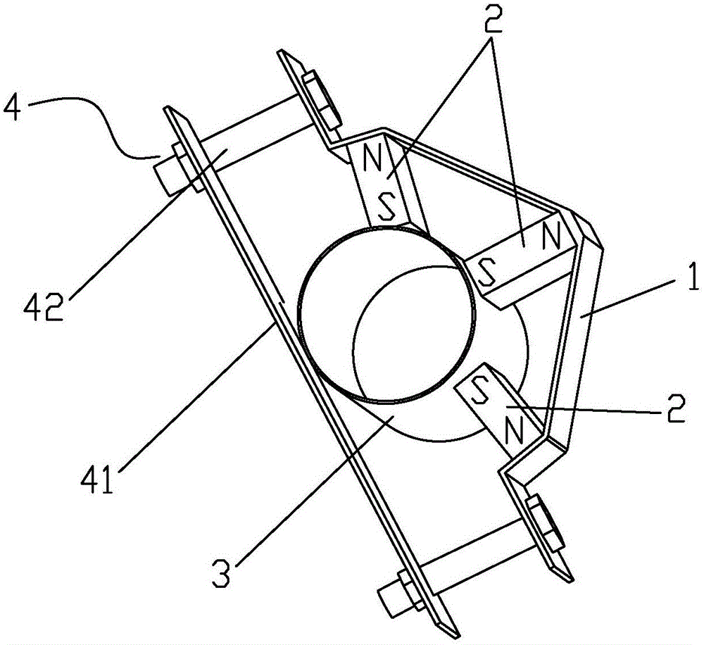
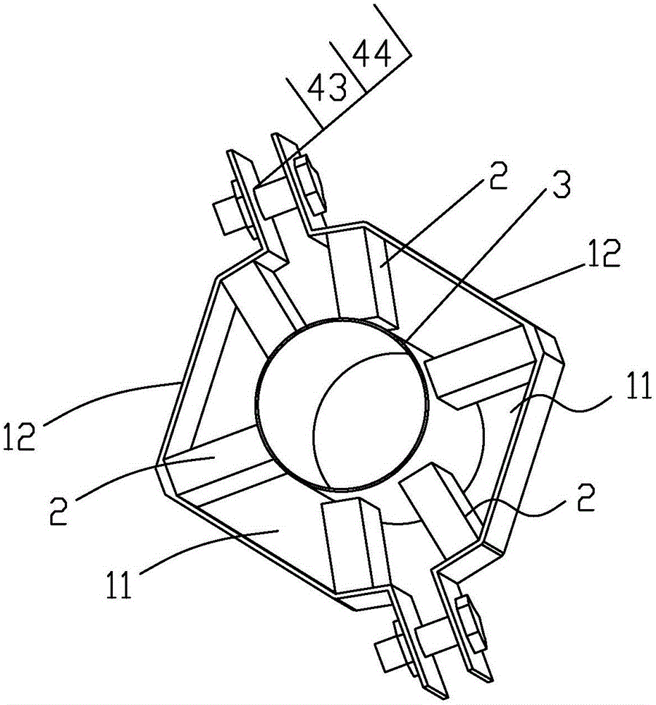
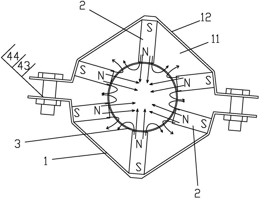
[0023] A magnetizer, comprising a support frame 1, the support frame 1 is provided with a plurality of mutually spaced permanent magnets 2, the number of the permanent magnets 2 is an odd number greater than 1, each of the One end of the permanent magnet 2 is connected to the support frame 1, and the other end is against the fluid pipeline 3. The polarity of the end of each permanent magnet 2 connected to the support frame 1 is the same, and the two adjacent permanent magnets 2 are close to the support frame. The distance between one end of the magnetizer 1 is greater than the distance between the two ends away from the support frame 1, and the magnetizer also includes a mounting device 4 for mounting it on the fluid pipeline 3. The support frame 1 is provided with a plurality of mutually spaced permanent magnets 2, one end of each permanent magnet 2 is connected to the sup...


PUM


Abstract

The invention discloses a magnetizer which comprises a supporting frame (1). A plurality of permanent magnets (2) are arranged on the supporting frame (1) at intervals. The number of the permanent magnets (2) is an odd number larger than 1. One end of each permanent magnet (2) is connected with the supporting frame (1), and the other end of each permanent magnet (2) abuts against a fluid pipeline (3). The polarities of the ends, connected to the supporting frame (1), of the permanent magnets (2) are the same. The distance between the ends, close to the supporting frame (1), of every two adjacent permanent magnets (2) is larger than the distance between the ends, away from the supporting frame (1), of the permanent magnets (2). The magnetizer further comprises an installation device (4) for installing the magnetizer on the fluid pipeline (3). The magnetizer is simple in structure, low in cost, convenient to construct in practical application and obvious in magnetizing effect on various kinds of fluid in pipelines.

Description

【Technical field】 [0001] The invention relates to a magnetizer. 【Background technique】 [0002] For a long time, many scientific research institutions and experts and scholars at home and abroad have carried out research experiments on magnetization technology through various experiments, and have concluded that after magnetization, water molecules can be refined, softened, the pH value of buffered water can be balanced, and pipeline fouling can be dissolved and removed. Magnetized water can increase production and reduce pests and diseases when used in various plant planting and poultry breeding. After magnetizing hydrocarbon fuels, internal combustion engines can burn more fully, which can achieve energy saving and emission reduction. Install magnetization on crude oil pipelines in oil fields. The device can reduce the sedimentation and clogging of sludge and paraffin, and the use of magnetization technology in the human body for magnetic therapy to obtain health care effe...

Claims


Application Information

Patent Timeline
IPC IPC(8): C02F1/48H01F13/00
Inventor 余任文
Owner 余任文
Features
  • R&D
  • Intellectual Property
  • Life Sciences
  • Materials
  • Tech Scout
  • Unparalleled Data Quality
  • Higher Quality Content
  • 60% Fewer Hallucinations
Learn More