Bearing type RV speed reducer

A technology of reducer and bearing, which is applied in the direction of mechanical equipment, transmission parts, gear transmission, etc., can solve the problems of heavy load on the central input shaft and structural damage, etc., and achieve the effect of smooth driving and stable structure

Inactive Publication Date: 2015-11-11
FUJIAN LIDONG PRECISION MACHINERY
View PDF6 Cites 6 Cited by
  • Summary
  • Abstract
  • Description
  • Claims
  • Application Information

AI Technical Summary

Problems solved by technology

[0004] Since the input shaft is a power shaft, which directly drives the swing of the eccentric wheel and the cycloid wheel, there are also problems with the stabi

Method used


Image

  • Bearing type RV speed reducer
  • Bearing type RV speed reducer
  • Bearing type RV speed reducer

Examples


Example Embodiment

[0042] The specific implementation of the present invention will be described below in conjunction with the drawings and embodiments:

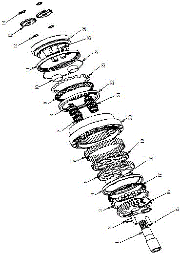
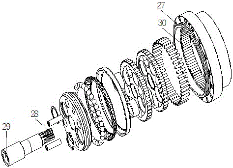
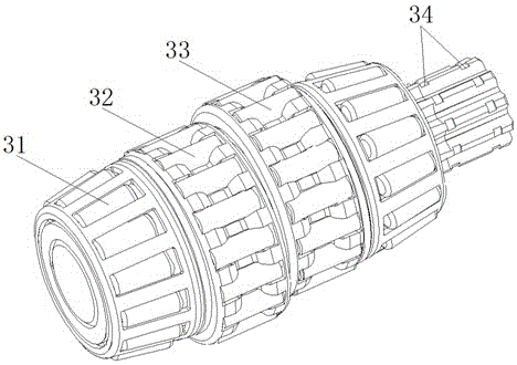
[0043] Such as Figure 1-9 As shown, it shows a specific embodiment of the present invention. As shown in the figure, a bearing-type RV reducer includes a body 20 with a through hole at the center of the body; and also includes a rotary mounting on the wall of the through hole of the body. Bearing seat 16 and footed bearing seat 26; two cycloidal wheels 19 are arranged parallel between the bearing seat and the footed bearing seat, and needle rollers 6 are arranged between the cycloidal wheel and the wall of the through hole;

[0044] As shown in the figure, the bearing seat 16, the footed bearing seat 26 are connected by fastening components; the bearing seat 16, the footed bearing seat 26 and the cycloid 19 are provided with an input shaft hole located in the center correspondingly, symmetrical Eccentric shaft holes arranged on both sides of the ...


PUM


Abstract

Disclosed in the invention is a bearing type RV speed reducer. The structure of the speed reducer is stable and the power transmission process is smooth and reliable. The bearing type RV speed reducer comprises a body; and a through hole is formed in the center of the body. In addition, the speed reducer also includes a bearing seat and a foot-contained bearing seat, wherein the bearing seat and the foot-contained bearing seat are installed at the wall of the through hole of the body in a rotating mode. Two cycloidal gears are arranged between the bearing seat and the foot-contained bearing seat in parallel; and roller pins are arranged between the cycloidal gears and the wall of the through hole. Input shaft holes located at the centers as well as eccentric shaft holes symmetrically formed in the two sides of the input shaft holes are correspondingly formed in the bearing seat, the foot-contained bearing seat, and the cycloidal gears; and are symmetrically formed in the two sides of the input shaft hole. An input shaft is installed at the walls of the input shaft holes in a rotating mode. Eccentric shafts contain eccentric wheels cooperating with the eccentric shaft holes of the two cycloidal gears. Gear wheels engaged with each other are installed at end portions, approaching the foot-contained bearing seat, of the eccentric shafts and the input shaft. The diameter of the gear wheel of the input shaft is smaller than the gear wheel diameters of the eccentric shafts. A blind hole for assembling a power shaft is formed in one end, far away from the foot-contained bearing seat, of the input shaft; and a key groove is formed in the wall of the blind hole.

Description

technical field [0001] The invention relates to a reducer, especially an RV reducer designed for the field of robots. Background technique [0002] In the field of high-precision drive devices for robots, we need high-precision reducers to drive motion; this type of reducer has a large reduction ratio and can stabilize output; in this field, the planetary gear reduction mechanism was used early, which includes Multiple input shafts realize power output through the transmission and cooperation of planetary gears; later, due to the poor stability and durability of the planetary gear reduction mechanism, it is changed to a mechanism that cooperates with cycloidal wheels and needle rollers to realize the components of the reducer; [0003] The current cooperation between the cycloidal wheel and the needle roller (the needle roller assembled in the pin gear housing) is to drive the cycloidal wheel to swing by setting the eccentric wheel on the center input shaft. When the cycloid...

Claims


Application Information

Patent Timeline
IPC IPC(8): F16H1/32F16H57/08F16H1/46F16H57/029
CPCF16H1/32F16H1/46F16H57/029F16H57/08F16H2001/323
Inventor 蔡伟强
Owner FUJIAN LIDONG PRECISION MACHINERY
Why Eureka
Try Eureka