System for laminating optical film and method of manufacturing display unit using the same

An optical film and optical film layer technology, applied in lamination systems, chemical instruments and methods, optical components, etc., can solve the problems of increasing the length of the process line and reducing the space efficiency, and achieve the effect of improving the process efficiency

Active Publication Date: 2015-11-11
SHANJIN OPTOELECTRONICS SUZHOU CO LTD
View PDF6 Cites 5 Cited by
  • Summary
  • Abstract
  • Description
  • Claims
  • Application Information

AI Technical Summary

Problems solved by technology

[0007] In order to carry out this additional step, the tool for rotating the panel or the optical film needs to be added, and

Method used


Image

  • System for laminating optical film and method of manufacturing display unit using the same
  • System for laminating optical film and method of manufacturing display unit using the same
  • System for laminating optical film and method of manufacturing display unit using the same

Examples


Embodiment Construction

[0055]Hereinafter, preferred embodiments of the present disclosure will be described in detail with reference to the accompanying drawings. Before setting forth, it should be understood that the terms used in the specification and appended claims should not be construed as being limited to their ordinary and dictionary meanings, but rather by allowing the inventor to define the terms as appropriate for best description The principles are explained based on the meanings and concepts corresponding to the technical solutions of the present disclosure. Accordingly, the descriptions set forth herein are preferred examples for purposes of illustration only, and are not intended to limit the scope of the present disclosure, and it should be understood that other equivalents can be obtained without departing from the spirit and scope of the present disclosure. ways and ways to improve.

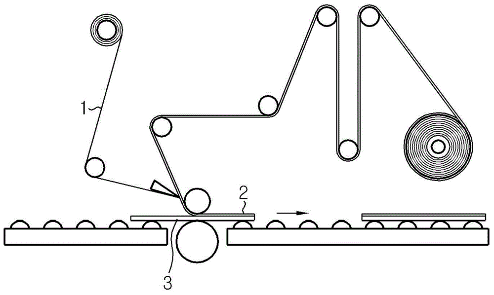
[0056] First, refer to Figure 5 , describing an overall structure of a system for laminating an...


PUM


Abstract

A system for laminating an optical film according to an exemplary embodiment of the present invention includes a panel transfer unit, a first laminate unit, a first laminate unit mounted on a transmission line of the panel to provide an optical film laminated on a first surface of the panel, a first surface of the panel, and a second laminate unit mounted on a transmission line parallel to the panel.

Description

technical field [0001] The present disclosure relates to a system for laminating an optical film and a method of manufacturing a display unit using the system, and more particularly, to a system for attaching an optical film and a method of manufacturing a display unit using the system, which can Process efficiency is increased in a process of attaching an optical film on both surfaces of a panel constituting a display device. [0002] This application claims priority from Korean Patent Application No. 10-2014-0047336 filed in Korea on Apr. 21, 2014, the disclosure of which is hereby incorporated by reference into this application. Background technique [0003] For use in a display device, a display unit realized by attaching an optical film such as a polarizing film to both surfaces of a panel is manufactured with a manufacturing system, figure 1 Conceptually showing part of a system for manufacturing a display unit according to the prior art, and figure 2 A process of m...

Claims


Application Information

Patent Timeline
IPC IPC(8): G02B1/10G02B5/30B32B37/10B32B37/14B32B38/00B32B39/00
CPCB29C65/02B32B37/22B32B38/0004B32B39/00B32B2457/20
Inventor 金景植申龙燮柳在汉李石宰张应镇朱元喆朴天湖
Owner SHANJIN OPTOELECTRONICS SUZHOU CO LTD
Why Eureka
Try Eureka