Micro-motion induction switch

A touch switch and switch technology, applied in the field of sensors, can solve problems such as poor contact, lack of overheating protection, and short service life, and achieve the effects of reducing the possibility of false triggering, novel and reasonable structure, and clear on and off states

Active Publication Date: 2015-11-11
AUPU HOME STYLE CORP LTD
View PDF5 Cites 4 Cited by
  • Summary
  • Abstract
  • Description
  • Claims
  • Application Information

AI Technical Summary

Problems solved by technology

[0004] 1. When there are many parts driving the micro-sensor switch, a high assembly tolerance is required between the parts during assembly, resulting in difficult assembly and poor stability;
[0005] 2. Although the induction is sensitive, the induction signal and the on or off signal are often not accurately identified, so it is difficult to access the control system
[0006] 2. The existing micro-motion sensor switch generally has a spring in the attachment of the trigger to realize the switch. The spring is linearly stretched or compressed with the pressure fluctuation, not only unstable when vibrating, but also easy to change due to fatigue, so Poor stability, prone to accidental touch or poor contact, poor use effect
[0007] 3. The existing micro-motion sensor switch not only lacks overheating protection, but its own safety is not high, and the internal structure is complicated, and the layout is too compact. Even if the overheating protection circuit is installed, the overall structure is too complicated and the cost is high.
[0008] 4. The external overheating protection circuit usually uses a fuse, which will be blown when the current is too large, and it will be repaired once it is damaged, and the service life is short

Method used


Image

  • Micro-motion induction switch
  • Micro-motion induction switch
  • Micro-motion induction switch

Examples


Embodiment

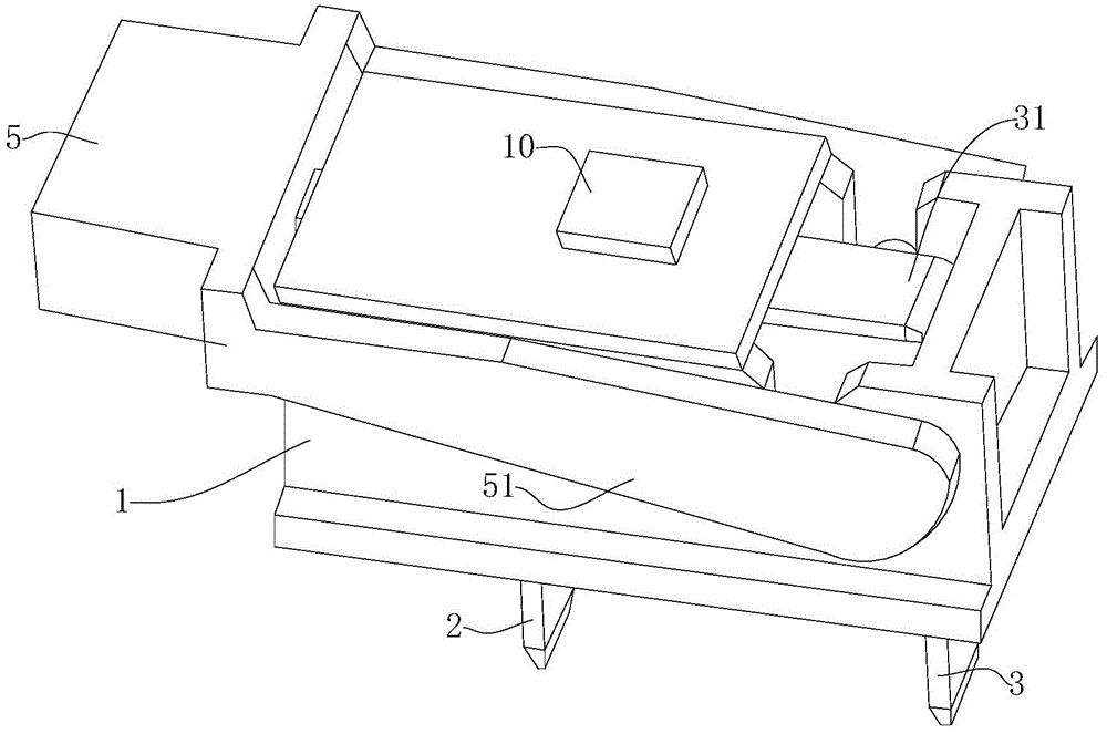
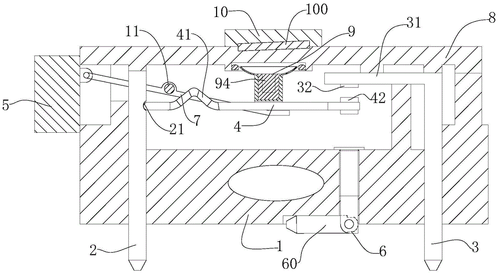
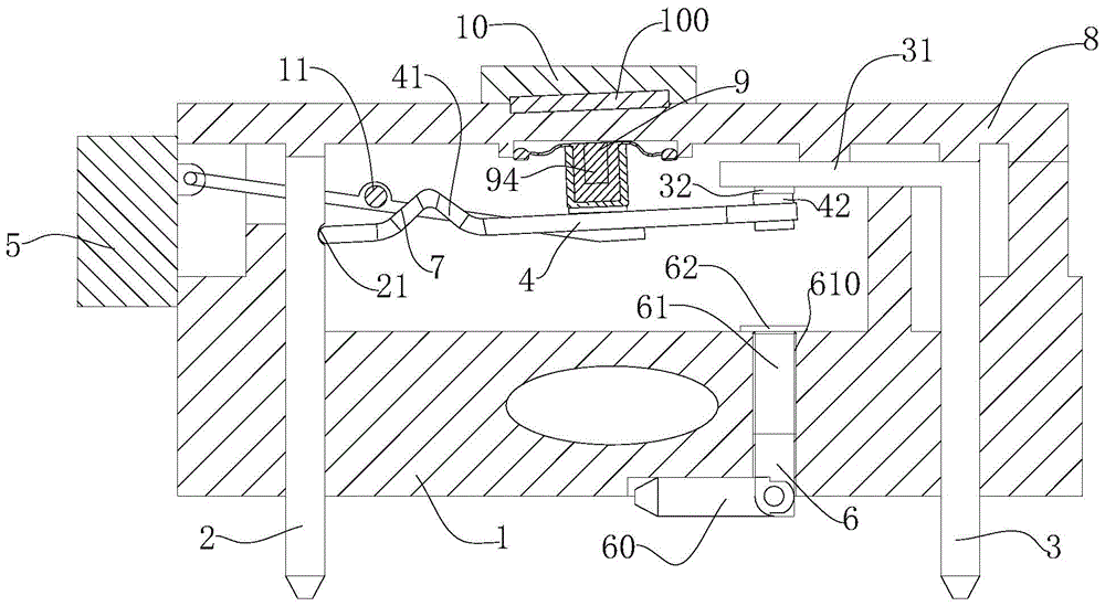
[0040] Such as Figure 1-9 The micro-motion sensor switch shown is composed of a housing 1, a touch switch and a touch pressure block 5. The top of the housing 1 is an upper cover 8, and two wing plates 51 are provided on one side of the touch block 5, and the two wing plates 51 are symmetrically spaced apart.

[0041] The inner side of the distal end of the wing plate 51 is provided with a T-shaped clip connection end 52, and the two sides of the housing 1 corresponding to the clip connection end 52 are respectively provided with a notch 13 hinged to the clip connection end. The touch pressure block 5 is movably hinged on the outside of the housing 1 through a snap connection end 52 at its distal end, and is connected to a touch switch. The touch pressure block 5 can move up and down with the pressure, thereby driving the touch switch to complete the on and off action. The above-mentioned tact switch main body is installed in the housing 1, and the upper cover 8 covers the hou...


PUM


Abstract

The invention relates to a micro-motion induction switch which can trigger a switch by applying pressure. The micro-motion induction switch comprises a shell, a trigger switch and a trigger press block. One side of the trigger press block is provided with two wing plates, and the trigger press block is movably hinged outside the shell through the two wing plates. The trigger switch comprises a first pin, a second pin, a movable contact, an elastic reset assembly and a connection rod. An upper end of the second pin is provided with a transverse folding part. A fixed end of the movable contact is clamped on an upper part of the first pin. A free end of the movable contact is arranged below the transverse folding part. The movable contact is provided with a raised folding contraction section. An outer end of the connection rod is hinged to the trigger press block. A middle part of the connection rod is hinged in the shell. An inner end of the connection rod extends below the movable contact and is connected to the movable contact. An upper end of the elastic reset assembly is connected on an inner wall of the top side of the shell, and a lower end of the elastic reset assembly is fixed on the middle part of the movable contact. The micro-motion induction switch is novel and reasonable in structure, good in stability, sensitive to trigger and induce, not prone to false triggering, and high in safety.

Description

Technical field [0001] The invention belongs to the field of sensors, and particularly relates to a micro-motion induction switch that triggers the switch by applying pressure. Background technique [0002] At present, micro-motion induction switches are commonly used in many fields, especially in many control systems, as sensors and actuators, so their sensitivity, stability and safety are very important. [0003] At present, the micro-motion sensor switch triggered by applying a small pressure has the following disadvantages: [0004] 1. When there are many parts that drive the micro-motion sensor switch, higher assembly tolerances are required between the parts during assembly, which results in assembly difficulties and poor stability; [0005] 2. Although the sensing is sensitive, the sensing signal and the on or off signal are often not accurately identified, so it is difficult to access the control system. [0006] 2. Existing micro-motion induction switches generally have spring...

Claims


Application Information

Patent Timeline
Patent Type & Authority Applications(China)
IPC IPC(8): H01H13/20H01H13/12
CPCH01H13/12H01H13/20
Inventor 朱正直
Owner AUPU HOME STYLE CORP LTD
Why Eureka
Try Eureka