Intra uterine device place-in apparatus and operation method thereof

An operation method and IUD technology, applied in the field of insertion devices, can solve problems such as IUD fixation, jumping, and inconvenient use, and achieve the effects of ensuring birth control effects, avoiding displacement, and ensuring placement effects

Inactive Publication Date: 2015-11-18
胡友斌
View PDF8 Cites 2 Cited by
  • Summary
  • Abstract
  • Description
  • Claims
  • Application Information

AI Technical Summary

Problems solved by technology

[0003] Among them, the front end of the upper ring fork is the fork head and the rear end is the handle. It is used by many doctors because of its simple structure and smooth operation. However, during the operation process, the IUD cannot be fixed. It is easy to slip off and has a low success rate; it is usually only suitable for ring-shaped IUDs, but it is not suitable for Y-shaped and M-shaped IUDs that appear later. When using the IUD, the placement direction of the IUD in the uterine cavity cannot be ensured, which will affect the effect of birth control
[0004] The upper ring forceps are hinged by two forceps arms through the rotating shaft to form a pincer shape. During operation, the forceps head is used to hold the IUD into the uterine cavity. When the upper ring forceps is moved out, it is difficult to ensure that the forceps head is completely separated from the IUD. During the process, the IUD is firmly clamped, and the two usually have a large clamping contact area. Therefore, during the removal process of the upper ring forceps, the clamp head is easy to carry the IUD and cause displacement, which makes the IUD break away from the expected correct position. Affects the placement effect of the IUD; at the same time, it has a better clamping effect for the ring-shaped IUD, but for non-ring-shaped IUDs such as M-shaped and Y-shaped, there is no better clamping posit...

Method used


Image

  • Intra uterine device place-in apparatus and operation method thereof
  • Intra uterine device place-in apparatus and operation method thereof
  • Intra uterine device place-in apparatus and operation method thereof

Examples


Embodiment Construction

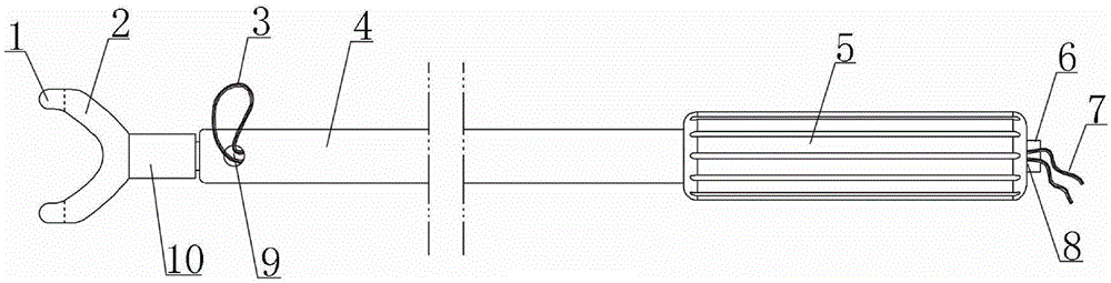
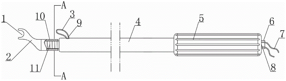
[0035] like figure 1 , 2 , 4 and 6, an IUD insertion device disclosed in the present invention is composed of a handle rod, a fork head, a fixed pull wire 7, a wire pressure plug 6 and a pull wire guide wire 15.

[0036] like figure 1 , 2 As shown in , 6, the shank is composed of a slender rod 4 and a shank 5 at the rear. The hole 8, the wire inlet hole 9 and the wire outlet hole 8 are communicated through a fixed pull wire channel 19 in the handle rod; the rod part 4 and the handle part 5 can be integrally formed, and the two are preferably made of medical plastic, wherein the handle The part 5 is thicker than the rod part 4, and the side wall of the handle part 5 is provided with anti-slip lines to facilitate the grasping operation; in order to facilitate the threading operation, the wire inlet hole 9, the wire outlet hole 8 and the fixed cable channel 19 are connected. The transition should be smooth;

[0037] like figure 1 , 2 As shown in , 5 and 6, the fork head is...


PUM


Abstract

The invention belongs to the medical apparatus, and discloses an Intra uterine device place-in apparatus comprising a handle bar formed by a bar portion and a handle portion; a side wall of the front portion of the rod portion is provided with a wire inlet; the rear end of the handle portion is provided with a wire outlet; the wire inlet is connected with the wire outlet through a fixing stay wire channel; a fork head is arranged on the front end of the handle bar, comprises two fork arms, and the front end of the fork arm is provided with a holder slot; two ends of the fixing stay wire respectively turn around two sides of the rear end of the Intra uterine device, the fixing stay wire then enters the fixing stay wire channel through the wire inlet, and exits the wire outlet; a press wire plug inserts the wire outlet so as to tighten and fix two ends of the fixing stay wire; a stay wire guide wire is used for guiding the fixing stay wire. The Intra uterine device place-in apparatus is simple in structure, low in cost, is disposable, safe and clean, convenient and fast in operation, good in applicability, and can be applied to Intra uterine devices of random shapes; the Intra uterine device place-in apparatus can adjust a direction of the Intra uterine device in the uterine cavity, so the Intra uterine device can be placed in a best position, thus ensuring birth control effect.

Description

technical field [0001] The present invention relates to a medical instrument, in particular to an implantation device which can be applied to various shapes of contraceptive devices. Background technique [0002] The IUD is a contraceptive device placed in the uterine cavity. It is placed in the uterine cavity of women of childbearing age to achieve the purpose of abortion and contraception through mechanical stimulation and chemical interference. Because it does not inhibit ovulation, it does not affect women. Endocrine system, avoiding the adverse reactions of general drug contraception, coupled with its economical and effective, easy to pick and place, and thus become one of the most commonly used contraceptive measures, especially in my country. The operation of placing the IUD in the uterus is commonly known as "upper ring", which usually requires the use of an upper ring fork, upper ring forceps or a cannula-like insertion device to complete the operation. [0003] Amo...

Claims


Application Information

Patent Timeline
IPC IPC(8): A61F6/18
Inventor 王才丰
Owner 胡友斌
Why Eureka
Try Eureka