Movable penholder

A pen holder and pen cover technology, which is applied in the field of stationery, can solve the problems of small space for the rotation shaft of the pen holder and limited application range, and achieve the effects of simple structure, multiple uses and easy operation.

Inactive Publication Date: 2009-12-02
谈发来
View PDF1 Cites 3 Cited by
  • Summary
  • Abstract
  • Description
  • Claims
  • Application Information

AI Technical Summary

Problems solved by technology

The pen holder is attached to the stationery box, and its application range is limited. In addition, the space for the shaft of the pen holder is small

Method used


Image

  • Movable penholder

Examples


Embodiment Construction

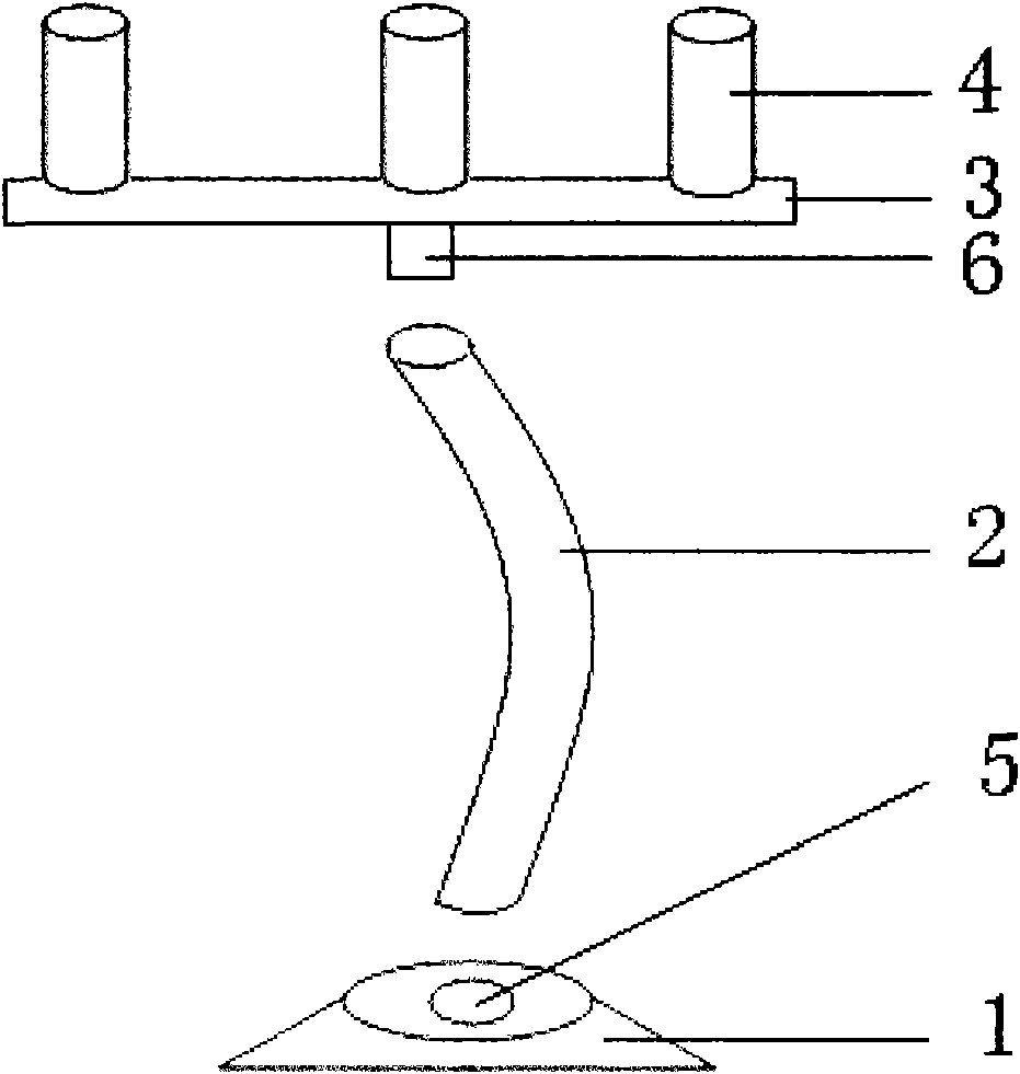
[0008] like figure 1 As shown, the movable pen holder includes a base 1 , a metal hose 2 , a bearing rod 3 and a pen cover 4 , and the base 1 and the bearing rod 3 are connected through the metal hose 2 . The base 1, the carrying rod 3 and the pen cover 4 are made of metal. A socket 5 is provided on the base 1 . The lower end of the metal hose 2 is inserted into the socket 5 of the base 1 . A tenon 6 is provided below the bearing rod 3 . The tenon 6 below the bearing bar 3 is inserted into the upper end of the metal hose 2 . The carrying rod 3 is provided with a pen case 4 . The carrying rod 3 is fixedly connected with the pen case 4 . The carrying rod 3 and the pen cover 4 can be welded into an integral structure. Pen and pencil can be inserted in the pen cover 4, and the writing brush can be suspended on the bearing bar 3 with the pen cover 4 as a stake. The movable pen holder can adjust the range and direction according to the needs of use.


PUM


Abstract

The invention discloses a movable penholder, and aims to provide a penholder with large adjustable amplitude. The invention adopts the technical proposal that a metal hose is used as an element for adjusting the movable amplitude. The movable penholder comprises a base, the metal hose, a bearing rod and a pen cap, and the base and the bearing rod are connected through the metal hose. The technical proposal adopted by the invention has simple operation; and the movable penholder has a simple structure, is multifunctional and is convenient to adjust the height and direction.

Description

technical field [0001] The present invention relates to stationery. Background technique [0002] The description with the application number 200520083727.7 discloses a rotating pen stand, which is provided with a rotating stationery box on a fixed base, and is characterized in that a hollow rotating shaft is connected to the center of the bottom surface of the stationery box, and the top surface of the fixed base The center position of the shaft is connected with a shaft support sleeve; the hollow shaft is installed in the shaft support sleeve, and the outer diameter of the shaft is a sliding fit with the inner diameter of the sleeve; the inner hole of the hollow shaft is equipped with a round plug nail, and the inner hole of the hollow shaft It is a tight fit with the round plug nail. The pen holder exists attached to the stationery box, and its application range is limited. In addition, the space for the rotating shaft of the pen holder is small. Contents of the invent...

Claims


Application Information

Patent Timeline
Patent Type & Authority Applications(China)
IPC IPC(8): B43M17/00B43M99/00
Inventor 谈发来
Owner 谈发来
Why Eureka
Try Eureka