Automatic loading mechanism of pin shaft

An automatic feeding and pin technology, which is applied in the direction of conveyor objects, transportation and packaging, etc., can solve the problem of low efficiency of manual feeding

Inactive Publication Date: 2015-11-18
CHONGQING GANGQIAN MACHINERY
View PDF0 Cites 16 Cited by
  • Summary
  • Abstract
  • Description
  • Claims
  • Application Information

AI Technical Summary

Problems solved by technology

[0003] The present invention intends to provide a pin shaft automatic feeding mechanism to solve the problem of low efficiency of manual feeding

Method used


Image

  • Automatic loading mechanism of pin shaft

Examples


Embodiment Construction

[0011] The present invention will be described in further detail below by means of specific embodiments:

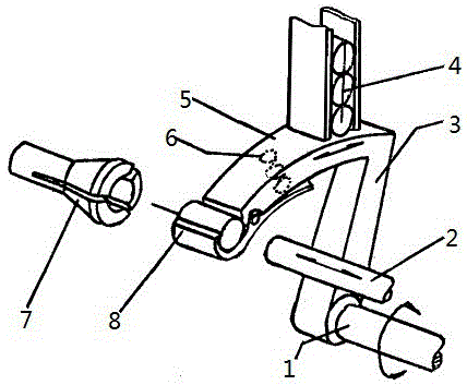
[0012] The reference signs in the drawings of the description include: transmission shaft 1, push rod 2, first support rod 3, pin shaft 4, second support rod 5, compression spring 6, collet 7, splint 8.

[0013] The example is basically as attached figure 1 As shown: the pin shaft automatic feeding mechanism of this embodiment includes a swing rod, and the push rod 2 is arranged on one side of the swing rod. The push rod 2 can reciprocate along a horizontal straight line driven by the piston rod of the cylinder. On the other side of the swing rod, it is used to clamp the pin shaft.

[0014] The feed bin is vertically arranged, and the pin shaft 5 is placed in the feed bin up and down successively along the vertical direction, and the outlet of the feed bin is arc-shaped. The swing rod is located below the feed bin, and the swing rod includes a first strut 3 and a second...


PUM


Abstract

The invention discloses an automatic loading mechanism of a pin shaft to solve the problem of low manual loading efficiency in the prior art. The mechanism comprises a swing rod arranged below a bin, wherein an outlet of the bin is arched; the swing rod comprises a first support rod and a second support rod formed to an L shape and integrally molded; the first support rod is driven through power to perform the reciprocating rotation; the upper part of the second support rod is a convex arched slide table; the convex arched slide table and the outlet have the same curvature; the convex arched slide table can slide along the outlet when the first support rod swings; a groove is formed in the end part of the second support rod at the side of the convex arched slide table, and can swing below the outlet; a push rod capable of performing reciprocating linear motion is arranged at one side of the swing rod; the other side of the swing rod is a spring chuck; and the axles of the spring chuck, the groove and the push rod are on one straight line.

Description

technical field [0001] The invention relates to the processing technology of agricultural machinery parts, in particular to an automatic feeding mechanism for pin shafts. Background technique [0002] The structure of the pin shaft includes a cylindrical shaft section and a flange at one end of the shaft, and a hole is usually processed at the other end of the shaft for connection during use. For micro-tillers among existing agricultural machinery, a pin shaft is usually used to connect the rotary tiller cutter and the main shaft, and the pin shaft is locked with a cotter pin, which is reliable in operation and easy to disassemble. The processing technology of the pin shaft includes blanking, heat treatment, inspection, clamping outer circle, turning plane, drilling, turning plane, large outer circle, chamfering, inspection, drilling, deburring, surface treatment and finished product inspection. Since the hole of the pin shaft is opened at the end, it is usually clamped wit...

Claims


Application Information

Patent Timeline
Patent Type & Authority Applications(China)
IPC IPC(8): B65G47/82
Inventor 唐仁伟
Owner CHONGQING GANGQIAN MACHINERY
Why Eureka
Try Eureka