
Gantry-type road cone automatically deploying and retracting device

An automatic retractable, gantry-type technology, applied in the directions of roads, roads, road signs, etc., can solve the problems of high labor intensity, low work efficiency, and hidden dangers of operation safety, so as to improve the efficiency of highway operation and eliminate hidden dangers of operation safety. , the effect of reducing labor intensity

Inactive Publication Date: 2015-11-18
SHANGHAI DIANJI UNIV
View PDF5 Cites 4 Cited by
  • Summary
  • Abstract
  • Description
  • Claims
  • Application Information

AI Technical Summary

Problems solved by technology

This kind of operation method has problems such as slow operation speed, high labor intensity of workers, great hidden dangers of operation safety, inconsistent stacking intervals of traffic cones and low work efficiency, especially when working on urban expressways with large traffic volumes. At the same time It is also susceptible to interference from weather and environmental factors, and the risk factor is high in harsh environments such as heavy fog, heavy rainfall or thunderstorms
In recent years, some road cone vehicles have also appeared on the market, which can replace manual work to realize automatic retraction of road cones, but in use, it is also found that this type of road cone vehicle has problems such as complex structure and inconvenient operation.

Method used


Image

  • Gantry-type road cone automatically deploying and retracting device
  • Gantry-type road cone automatically deploying and retracting device
  • Gantry-type road cone automatically deploying and retracting device

Examples


Embodiment Construction

[0033] In order to make the object, technical solution and advantages of the present invention clearer, various embodiments of the present invention will be described in detail below in conjunction with the accompanying drawings. However, those of ordinary skill in the art can understand that, in each implementation manner of the present invention, many technical details are provided for readers to better understand the present application. However, even without these technical details and various changes and modifications based on the following implementation modes, the technical solution claimed in each claim of the present application can be realized.

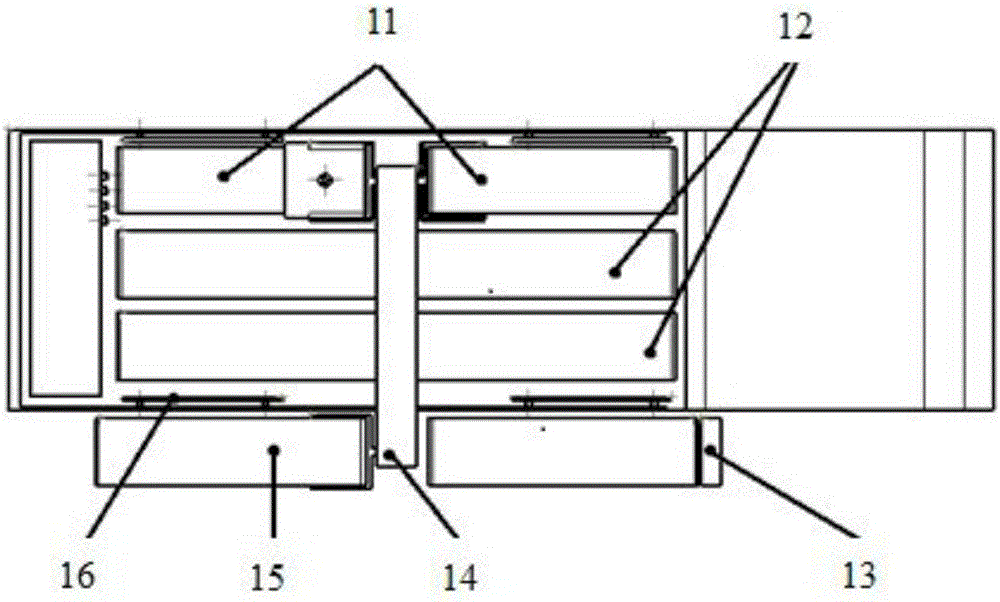
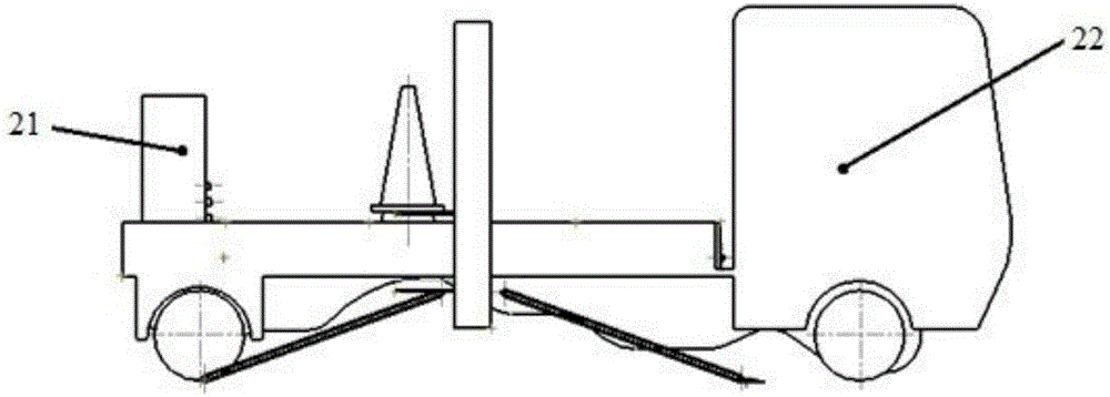
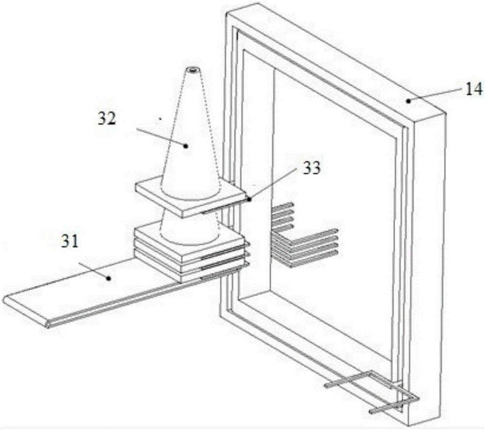
[0034] The embodiment of the present invention relates to a gantry type road cone automatic retracting device, which combines Figure 1 to Figure 11 shown.

[0035] Including: transmission device, transportation device and grounding delivery device, the transmission device is installed on the baffle plate of the vehicle bod...


PUM


Abstract

The present invention relates to a gantry-type road cone automatically deploying and retracting device. The gantry-type road cone automatically deploying and retracting device comprises a conveying device, a transporting device and a ground-connected conveying and placing device, wherein the transporting device also comprises push plates and a conveying crawler belt, and the push plates are installed on side baffles of a vehicle body while the conveying crawler belt is installed on a flat board of the vehicle body; the transporting device also comprises a track and support forks, and the support forks can move along the track; and the ground-connected conveying and placing device comprises a road cone deploying and retracting crawler belt forming a certain angle with the ground, and a micro poking and shoveling component. Manual replacement and recycling of the road cones during road maintenance is replaced, and full automation of road cone placement and recycling is realized. Risks of road operation are reduced, and personal safety of workers during working is raised. The road working efficiency is raised, and time is saved. Through constant-speed advancement of the vehicle and constant-speed movements of the device, equal-distance placement of the road cones is realized, and the aim of controlling distance among the road cones can be achieved by changing travelling speed of the vehicle.

Description

technical field [0001] The invention relates to the technical field of road traffic construction, in particular to a device for automatically placing and recovering road cones in expressway traffic. Background technique [0002] At present, during maintenance work on expressways in our country, in order to realize the temporary closure of the road, it is often necessary to use road cones to cut off the road. At present, most of the operations of retracting and retracting road cones are done manually. This kind of operation method has problems such as slow operation speed, high labor intensity of workers, great hidden dangers of operation safety, inconsistent stacking intervals of traffic cones and low work efficiency, especially when working on urban expressways with large traffic volumes. At the same time It is also susceptible to interference from weather and environmental factors, and the risk factor is high in harsh environments such as heavy fog, heavy rainfall or thun...

Claims


Application Information

Patent Timeline
Patent Type & Authority Applications(China)
IPC IPC(8): E01F9/014E01F9/70
Inventor 朱晓玄严明张喆程静张晓青侯培红
Owner SHANGHAI DIANJI UNIV
Learn More