
Combined type foundation pit supporting pile structure

A foundation pit support and combined technology, which is applied in basic structure engineering, excavation, construction, etc., can solve problems such as poor economic benefits and poor water-stopping effect, and achieve the effect of saving construction space, economic and social benefits.

Active Publication Date: 2015-11-18
KUNMING SURVEY DESIGN & RES INST OF CREEC
View PDF6 Cites 9 Cited by
  • Summary
  • Abstract
  • Description
  • Claims
  • Application Information

AI Technical Summary

Problems solved by technology

[0003] The purpose of the present invention is to overcome the problems of poor water-stopping effect and poor economic benefit of the pile row support structure in the above-mentioned prior art, and provide a kind of supporting function and water-stopping effect that can fully exert the two kinds of pile bodies, and can ensure construction Combined Foundation Pit Support and Retaining Pile Structure with Quality and Economic Benefits

Method used


Image

  • Combined type foundation pit supporting pile structure
  • Combined type foundation pit supporting pile structure
  • Combined type foundation pit supporting pile structure

Examples


Embodiment 1

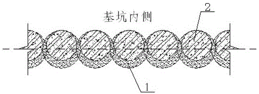
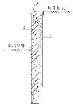
[0026] Embodiment 1: as figure 1 , 2 As shown in , 3, a combined foundation pit support pile structure is composed of a high-pressure jet grouting pile 1, a bored cast-in-situ pile 2 and a crown beam 3. The interlocking large-diameter high-pressure rotary grouting piles 1 are used as the water-proof curtain of the foundation pit, and the bored piles 2 are used as the foundation pit support and protection piles. After the quality of the pile 1 is basically stable, the construction of the bored pile 2 with a smaller diameter is carried out again at the same pile position, and the construction of the bored pile 2 is ensured on the premise that the occlusal part of the adjacent high-pressure jet grouting pile 1 is not occupied Next, inscribe the high-pressure jet grouting pile 1 on the side close to the foundation pit, and finally construct the crown beam 3 at the top of the pile, so as to jointly achieve the purpose of supporting the foundation pit and stopping water. High-pres...

Embodiment 2

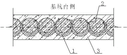
[0027] Embodiment 2: as figure 1 , 4 As shown in , 5, a combined foundation pit supporting pile structure is composed of high-pressure jet grouting pile 1, bored cast-in-place pile 2 and crown beam 3. The interlocking large-diameter high-pressure rotary grouting piles 1 are used as the water-proof curtain of the foundation pit, and the bored piles 2 are used as the foundation pit support and protection piles. After the quality of the pile 1 is basically stable, the construction of the bored pile 2 with a smaller diameter is carried out again at the same pile position, and the construction of the bored pile 2 is ensured on the premise that the occlusal part of the adjacent high-pressure jet grouting pile 1 is not occupied Next, inscribe the high-pressure jet grouting pile 1 on the side close to the foundation pit, and finally construct the crown beam 3 at the top of the pile, so as to jointly achieve the purpose of supporting the foundation pit and stopping water. The high-pr...


PUM


Abstract

The invention discloses a combined type foundation pit supporting pile structure. The combined type foundation pit supporting pile structure is composed of high-pressure jet grouting piles, cast-in-situ bored piles and a top beam. The high-pressure jet grouting piles which are engaged with one another and have large diameters are taken as a foundation pit waterproof curtain. The cast-in-situ bored piles are used as foundation pit supporting piles. The high-pressure jet grouting piles are constructed firstly, so that the waterproof curtain is formed; after the quality of the high-pressure jet grouting piles is almost stable, the cast-in-situ bored piles with small diameters are constructed again at the same positions as the high-pressure jet grouting piles, and it is guaranteed that the cast-in-situ bored piles are internally tangent to the high-pressure jet grouting piles on the sides close to a foundation pit on the premise that the portions, engaged with one another, of adjacent high-pressure jet grouting piles are not occupied during construction of the cast-in-situ bored piles; and finally, the top beam is arranged at the tops of the piles, and thus the purpose of supporting the foundation pit and the waterstop purpose are achieved. By the adoption of the combined type foundation pit supporting pile structure, the construction space of the foundation pit supporting structure can be effectively reduced. The combined type foundation pit supporting pile structure is particularly suitable for a foundation pit supporting project under the land shortage condition; due to the fact that the cast-in-situ bored piles with the small diameters are internally tangent to the high-pressure jet grouting piles with the large diameters, the combined effect of the two kinds of piles can be brought into full play.

Description

technical field [0001] The invention relates to a foundation pit support pile structure, in particular to a combined foundation pit support pile structure, which belongs to the technical field of building foundation pit engineering. Background technique [0002] Pile row support structure is one of the most commonly used foundation pit support systems at present. Its basic idea is: use bored piles as foundation pit support piles, and in areas with abundant groundwater, there are usually drilled piles between piles. After the pile, a high-pressure rotary spray pile is added to form a water-stop curtain. Among them, if you choose to add high-pressure jet grouting piles between the bored piles to occlude each other to form a water-stop curtain, due to the compact construction space and difficult control of construction quality, the precise occlusion effect is often not achieved within the vertical depth range, and the water-stop The effect is poor; if you choose to add one or ...

Claims


Application Information

Patent Timeline
Patent Type & Authority Applications(China)
IPC IPC(8): E02D17/04E02D19/18
Inventor 丁文云李光慧张可军杨翔罗云飞殷洪波罗胜利郭永发张红勇肖勇刚刘正初曹伟李贵民袁云洪田鲁鲁
Owner KUNMING SURVEY DESIGN & RES INST OF CREEC
Learn More