Pneumatic pump control device

A technology for control devices and pneumatic pumps, applied in pump control, pumps, piston pumps, etc., can solve the problems of increasing operating costs, reducing pump life, wasting compressed air power sources, etc., to improve service life, reduce start-stop frequency, The effect of optimized working conditions

Active Publication Date: 2015-11-18
王道宗
View PDF6 Cites 10 Cited by
  • Summary
  • Abstract
  • Description
  • Claims
  • Application Information

AI Technical Summary

Problems solved by technology

Pneumatic drainage pumps cannot be controlled automatically at present, and need to be supervised by people, otherwise they will continue to work after the water is drained, which will waste the power source of compressed air, reduce the service life of the pump, and increase up Operating costs
Some pneumatic pumps now only use a liquid level detection mechanism to control the operation and stop of the pneumatic pump, which often causes the pneumatic pump to start frequently, and the high and low water levels cannot be adjusted separately

Method used


Image

  • Pneumatic pump control device
  • Pneumatic pump control device
  • Pneumatic pump control device

Examples


Embodiment Construction

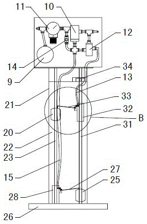
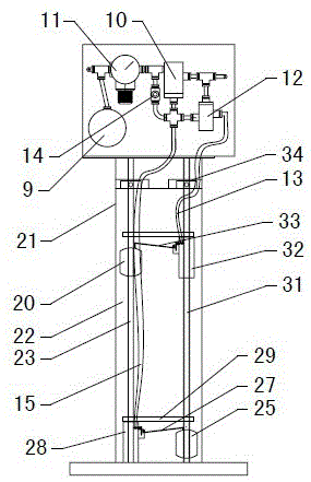
[0040] Figure 1~3 It is the best embodiment of the pneumatic pump control device. Figure 1~6 The present invention will be further explained.

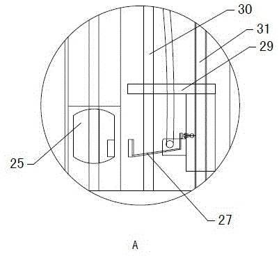
[0041] The pneumatic pump control device includes a pneumatic pump 5, an air supply pipeline 1, an air supply air control valve 3, and a control pipeline 7. The air supply pipeline 1 provides an air source for the pneumatic pump 5; the air supply air control valve 3 is set in the air supply pipe On line 1, control the on and off of the air supply line 1; the inlet of the control line 7 is connected to the air supply line 1 on the front side of the air supply air control valve 3, and the outlet is connected to the control air inlet of the air supply air control valve 3; control line 7 It is provided with a first control air control valve 10 and a second control air control valve 12, and also includes a low liquid level detection mechanism 19 and a high liquid level detection mechanism 18, which are connected to the first control air cont...


PUM


Abstract

A pneumatic pump control device comprises an air supply pipeline (1) and a control pipeline (7), wherein the air supply pipeline (1) and the control pipeline (7) are connected in parallel. The air supply pipeline (1) is provided with an air supply pneumatic control valve (3). An outlet of the control pipeline (7) is communicated with a control air inlet of the air supply pneumatic control valve (3). A liquid level control pipeline communicated with a water storage pool (16) is arranged on the control pipeline (7). The liquid level control pipeline comprises a low-liquid-level pneumatic control pipeline body and a high-liquid-level pneumatic control pipeline body. When the liquid level reaches a high liquid level, the high-liquid-level pneumatic control pipeline body and the low-liquid-level pneumatic control pipeline body are closed at the same time, and the air supply pneumatic control valve (3) is opened; when the liquid level reaches a low liquid level, the high-liquid-level pneumatic control pipeline body and the low-liquid-level pneumatic control pipeline body are used for exhausting air at the same time, and the air supply pneumatic control valve (3) is closed. Compressed air of a pneumatic pump is used as a power source of the control pipeline, operation is safe and reliable, and maintenance is not needed. The service life of the pneumatic pump control device is prolonged, and air sources are saved.

Description

Technical field [0001] A pneumatic pump control device belongs to the technical field of automatic drainage. Background technique [0002] At present, in low-lying places where there is a danger of explosion in mines and chemicals, only explosion-proof electric water pumps and pneumatic water pumps can be used. Flameproof electric water pumps also need explosion-proof switch control, which requires a large investment and a large maintenance workload. If the equipment is damaged or disrepaired, it loses its flameproof performance, and there is a danger of explosion. The pneumatic drainage pump cannot be controlled automatically now and needs to be supervised, otherwise it will continue to work after the water is drained, which will waste the compressed air power source, reduce the life of the pump and increase Up Operating costs. Nowadays, some pneumatic pumps only use one liquid level detection mechanism to control the operation and stop of the pneumatic pump, which often causes...

Claims


Application Information

Patent Timeline
Patent Type & Authority Applications(China)
IPC IPC(8): F04B49/02F04B9/12
Inventor 王道宗舒维宝王秀华
Owner 王道宗
Why Eureka
Try Eureka