Shock absorber

A technology of shock absorbers and elastic parts, which is applied in the field of shock absorbers, can solve the problems of low working efficiency, changes in the stiffness of shock absorbers, and difficulty in replacing shock absorbers, etc., and achieve the effects of prolonging service life and strong adaptability

Active Publication Date: 2015-11-18
ZHUZHOU TIMES NEW MATERIALS TECH
View PDF7 Cites 18 Cited by
  • Summary
  • Abstract
  • Description
  • Claims
  • Application Information

AI Technical Summary

Problems solved by technology

[0004] Therefore, when the user conducts on-site trial assembly and testing, it often occurs that the stiffness performance of the shock absorber cannot meet the vibration reduction requirements. In order to obtain shock absorbers with different stiffnesses, the manufacturer can only be asked to adjust the structure or rubber hardness to readjust the shock absorber. Vibrator stiffness, resulting in very low work efficiency, and the investment in development costs is also very high
[0005] In addition, during the long-term use of the shock absorber with rubber pad, the stiffness of the shock absorber will change greatly due to the aging and creep of the rubber pad.
This will result in the need to replace the shock absorber every once in a while
But in many cases it is not easy to replace the shock absorber

Method used


Image

  • Shock absorber
  • Shock absorber
  • Shock absorber

Examples


Embodiment 1

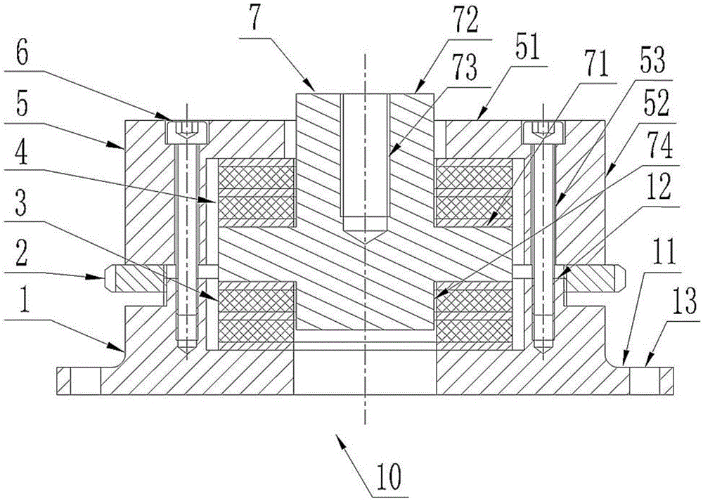
[0037] Such as figure 1 As shown, the shock absorber 10 in Embodiment 1 includes: a lower support 1 , an upper support 5 , a joint 7 , an upper elastic member 4 , a lower elastic member 3 , a screw 6 and an adjustment member 2 .

[0038] In this embodiment, the lower support 1 structure includes a lower cover 11 and a boss 12 . The lower cover 11 is configured substantially in the shape of a disc or a square disc. One end surface of the lower cover 11 is an upper surface. The boss 12 is ring-shaped and protrudes from the upper surface of the lower cover 11 in a direction away from the lower cover 11 . Preferably, the axis of the boss 12 coincides with the axis of the lower cover 11 . External threads are provided on the outer peripheral wall of the boss 12 . The external threads are distributed on the end of the boss 12 away from the lower cover 11 . The top of the boss 12 is also provided with a plurality of first screw holes. The plurality of first screw holes are even...

Embodiment 2

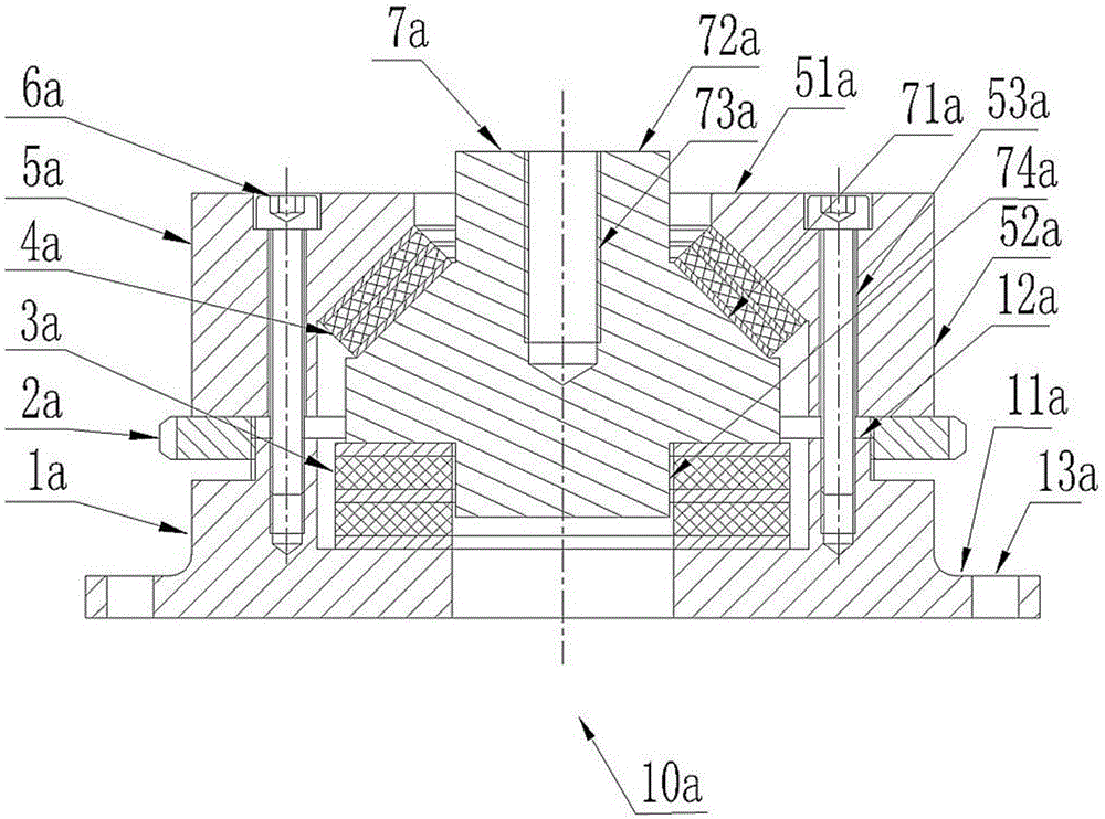
[0052] Such as figure 2 As shown, the shock absorber 10a in Embodiment 2 includes: a lower support 1a, an upper support 5a, a joint 7a, an upper elastic member 4a, a lower elastic member 3a, a screw 6a and an adjustment member 2a.

[0053] In this embodiment, the lower support 1a comprises a lower cover 11a and a boss 12a. The lower cover 11a is configured in a substantially disc shape or a square disc shape. One end surface of the lower cover 11a is an upper surface. The boss 12a is configured in a ring shape and protrudes from the upper surface of the lower cover 11a in a direction away from the lower cover 11a. Preferably, the axis of the boss 12a coincides with the axis of the lower cover 11a. External threads are provided on the outer peripheral wall of the boss 12a. The external threads are distributed, for example, at the end of the boss 12 a away from the lower cover 11 . The top of the boss 12a is also provided with a plurality of first screw holes. The plurali...

Embodiment 3

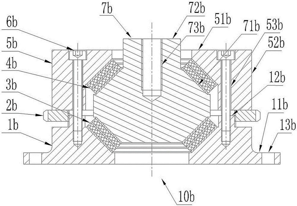
[0065] Such as image 3 As shown, the shock absorber 10b in Embodiment 3 includes: a lower support 1b, an upper support 5b, a joint 7b, an upper elastic member 4b, a lower elastic member 3b, a screw 6b and an adjustment member 2b.

[0066] In this embodiment, the lower support 1b comprises a lower cover 11b and a boss 12b. The lower cover 11b is configured in a substantially disc shape or a square disc shape. One end surface of the lower cover 11b is an upper surface. The boss 12b is ring-shaped and protrudes from the upper surface of the lower cover 11b in a direction away from the lower cover 11b. The inner wall of the boss 12b is an inner tapered surface facing away from the lower cover 11b. The inner tapered surface is preferably a conical surface. Preferably, the axis of the boss 12b coincides with the axis of the lower cover 11b. External threads are provided on the outer peripheral wall of the boss 12b. The external threads are distributed, for example, at the end...


PUM


Abstract

The invention relates to a shock absorber which comprises a lower supporting seat, an upper supporting seat, a joint, a lower elastic piece and an adjusting piece, wherein the upper supporting seat is tightly pressed towards the lower supporting seat; the joint comprises a core block and a supporting rod, the core block is arranged between the upper supporting seat and the lower supporting seat, and the supporting rod extends out of the core block and penetrates through the upper supporting seat; the lower elastic piece is arranged between the core block and the lower supporting seat, and the adjusting piece is used for adjusting the distance between the upper supporting seat and the lower supporting seat. The stiffness valve of the shock absorber can be adjusted on an installation site so that the demand for different shock absorbing stiffness is met, and the adaptability of the shock absorber is stronger than that of a common shock absorber. Meanwhile, after the shock absorber is used for a long time, the stiffness variation of the shock absorber caused by the aging and creep deformation of the lower elastic piece can be corrected by readjusting the distance between the upper supporting seat and the lower supporting seat, and therefore the service life of the shock absorber is relatively prolonged.

Description

technical field [0001] The invention relates to a shock absorber. Background technique [0002] As a clean energy, wind energy is being rapidly promoted around the world. At present, wind turbines have been developed into large megawatt models, and their structural types mainly include doubly-fed, semi-direct drive and direct-drive, among which doubly-fed wind turbines are the most widely used. When the wind power generating set is generating electricity normally, the rotation speed of the rotor of the generator is relatively high, and it will vibrate during normal operation. In double-fed and semi-direct drive wind turbines, a shock absorber is generally installed at the bottom of the generator for vibration isolation to prevent the input high-frequency vibration from being transmitted to the main frame through the generator and reduce the structural noise of the generator. [0003] However, there are many factors affecting the vibration frequency and amplitude of wind tu...

Claims


Application Information

Patent Timeline
Patent Type & Authority Applications(China)
IPC IPC(8): F16F15/08
CPCF16F15/08
Inventor 岳涛林胜胡伟辉杨超刘永苏泽涛谭虢刘权
Owner ZHUZHOU TIMES NEW MATERIALS TECH
Why Eureka
Try Eureka