
Porous medium dynamic water grouting device and method thereof

A technology of grouting device and porous medium, which is applied in measurement device, fluid dynamic test, testing of machine/structural components, etc., can solve the problems of low grouting pressure, experimental research, and inability to carry out the law of slurry diffusion under high pressure, etc. To achieve the effect of strong applicability and elimination of influence

Active Publication Date: 2017-09-05
SHANDONG UNIV
View PDF3 Cites 0 Cited by
  • Summary
  • Abstract
  • Description
  • Claims
  • Application Information

AI Technical Summary

Problems solved by technology

[0007] 1. It can only simulate a single plate fracture or Monte Carlo type cross fracture, and cannot simulate the dynamic water grouting process of porous media such as water-rich sand layers
[0008] 2. The grouting method of the water-rich sand layer is only determined according to the formation and groundwater conditions, and the migration law of the grout and dynamic water is not clear, so it is difficult to achieve a theoretical breakthrough
[0009] 3. The size of the test device is fixed, and the grouting pressure it bears is low, so it is impossible to carry out experimental research on the law of grout diffusion under high pressure
[0010] 4. The influence of the side wall of the test device on the slurry diffusion is usually ignored

Method used


Image

  • Porous medium dynamic water grouting device and method thereof
  • Porous medium dynamic water grouting device and method thereof

Examples


Embodiment Construction

[0038] The present invention will be further described below in conjunction with the accompanying drawings and embodiments.

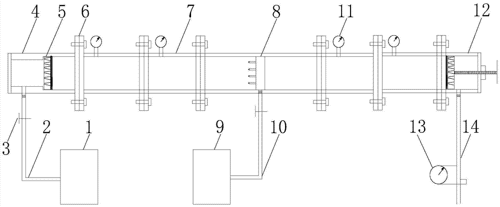
[0039] figure 1 Among them, a porous medium dynamic water grouting device and method thereof, including a grouting pump 1, a grouting chamber 4, a porous plate 5, a steel ring welded quick clamp joint 6, a single cylindrical steel pipe 7, and an automatic water supply tank 9. Sprinkler 8, pressure gauge 11, slurry chamber 12, ultrasonic flowmeter 13, etc. The slurry inlet chamber 4, the single cylindrical steel pipe 7 and the slurry outlet chamber 12 are connected as a whole through the steel ring welded quick clamp joint 6. The grouting pump 1 is connected to the slurry inlet chamber through the slurry inlet pipe 2 and the one-way stop valve 3. 4 are connected, the pulp inlet chamber 4 and the pulp outlet chamber 12 are both placed with a perforated plate 5, a pressure gauge 11 is placed on a single cylindrical steel pipe 7, and the automatic water su...


PUM


Abstract

The invention discloses a porous medium dynamic water grouting device and a method thereof, comprising a grouting device, a grouting chamber, a steel pipe, a grouting chamber, a connecting piece, a pressure measuring device and a flow measuring device, wherein the grouting device is connected into a The pulp chamber, the pulp inlet chamber is connected to one end of the steel pipe through a connecting piece, and the other end of the steel pipe is connected to the pulp outlet chamber through a connector. The connection between the pulp inlet chamber and the steel pipe and the connection between the pulp outlet chamber and the steel pipe are equipped with filter plates. A pressure measuring device is installed, and a sprinkler is installed inside the middle end of the steel pipe. The sprinkler is connected to the water inlet pipe, and the water inlet pipe is connected to the water supply device. A flow measuring device is provided on the tube. The invention eliminates the influence of the side wall of the device on the diffusion of the slurry, and can monitor the diffusion parameters of the slurry under different dynamic water parameters through a pressure gauge and an ultrasonic flowmeter.

Description

technical field [0001] The invention relates to a porous medium dynamic water grouting device and a method thereof. Background technique [0002] There are more and more water conservancy and hydropower projects, urban rail transit and cross-basin water diversion projects in China. The geological conditions faced by various engineering constructions are becoming increasingly complex. Geological disasters such as quicksand, piping, submerged erosion, and settlement deformation occur from time to time, posing a serious threat social benefits, engineering safety and ecological environment. Years of engineering practice have shown that the grouting method is an effective technical means to control various geological disasters. It has the characteristics of strengthening rock and soil structures, sealing hydraulic channels, and avoiding secondary disasters. At present, domestic and foreign scholars have developed a series of test devices, which have promoted the development of g...

Claims


Application Information

Patent Timeline
Patent Type & Authority Patents(China)
IPC IPC(8): G01M10/00
Inventor 李术才冯啸刘人太翟明华范建国郭信山王慧涛张兵
Owner SHANDONG UNIV
Learn More