Verification device for photoelectric current transformer and method thereof

A technology of current transformers and calibration devices, which is applied to measuring devices, instruments, and measuring electrical variables, etc., can solve problems such as high safety risks, time-consuming, and labor-consuming, and achieve small safety risks, large application quantities, and convenient acquisition Effect

Active Publication Date: 2015-11-18
STATE GRID CORP OF CHINA +2
View PDF13 Cites 6 Cited by
  • Summary
  • Abstract
  • Description
  • Claims
  • Application Information

AI Technical Summary

Problems solved by technology

However, this method needs to disconnect and connect the circuit once, and use a power source capable of outputting a large current, which is time-consuming, labor-intensive, and has a high safety risk.
More importantly, due to the limitation of the capacity of the added equipment, the method of applying the analog quantity on the primary side can generally only apply the analog quantity equivalent to the rated operating current at the maximum, which cannot fully meet the needs of the on-site verification of the DC control and protection system (maximum 5 times the rated current is required)
[0003] Existing verification method for current transformer is more, but generally is aimed at the electronic type current transformer of exchange, as the method for live verification of current transformer whose publication number is CN101408597A, its application number is CN200710046987; No. CN201120439554.3 patent discloses a high-voltage current transformer online calibration device; these calibration devices and methods cannot be applied to photoelectric current transformers

Method used


Image

  • Verification device for photoelectric current transformer and method thereof
  • Verification device for photoelectric current transformer and method thereof
  • Verification device for photoelectric current transformer and method thereof

Examples


Embodiment 1

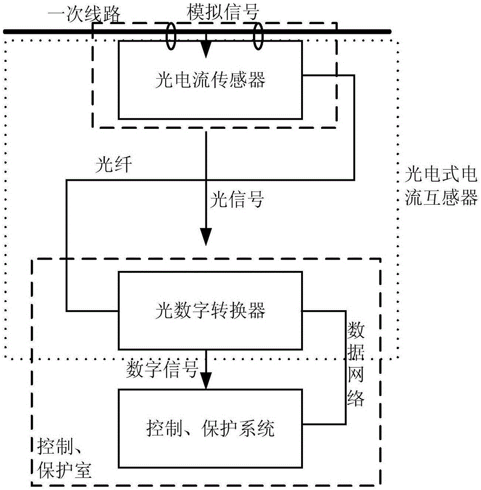
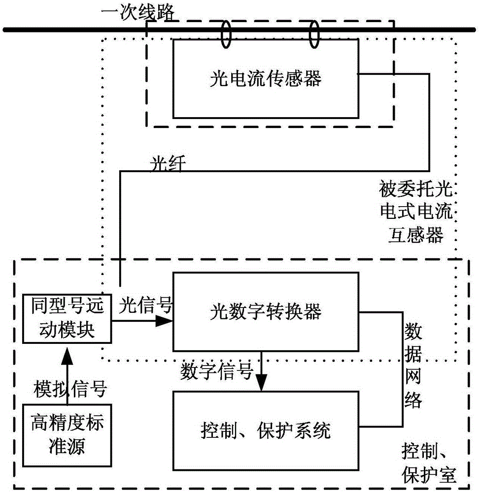
[0034] Such as image 3 A calibration device for a photoelectric current transformer, comprising a voltage source, a telecontrol module (for converting a voltage analog quantity into an optical signal), a photoelectric converter, and a signal acquisition module;

[0035] The photoelectric converter is the photoelectric converter of the photoelectric current transformer to be verified;

[0036] The voltage source is used to generate a voltage signal that simulates the output signal of the photocurrent sensor of the photoelectric current transformer to be verified, and the voltage signal is a voltage analog quantity;

[0037] The voltage source is connected with the telecontrol module to form a virtual measurement channel;

[0038] The telecontrol module converts the voltage analog quantity into an optical signal, and the optical signal is transmitted to the photoelectric converter through an optical fiber as a reference signal for verification, and the photoelectric converter ...


PUM


Abstract

The invention discloses a verification device for a photoelectric current transformer and a method thereof. The verification device comprises a voltage source, a motion module and a signal acquisition module. The voltage source is used for generating the voltage signal of the signal which is output by the photoelectric current sensor of the photoelectric current transformer to be verified. The voltage signal is a voltage analog quantity. The voltage source is connected with the motion module, thereby forming a virtual measuring channel. The motion module converts the voltage analog quantity to an optical signal. The optical signal is used as a reference signal for verification and is transmitted to the photoelectric converter of the photoelectric current transformer to be verified through an optical fiber. The signal acquisition module is an electric power control system or an electric power protecting system which is connected with the photoelectric converter of the photoelectric current transformer to be verified. The verification device for the photoelectric current transformer and the method thereof have advantages of easy application, low cost and high calibration precision.

Description

technical field [0001] The invention belongs to the technical field of electrical engineering, and relates to a calibration device and method for a photoelectric current transformer. Background technique [0002] With the popularization of (ultra) high-voltage direct current transmission technology, the application of photoelectric current transformers in power systems is also increasing. As the most important state quantity of (Ultra) HVDC transmission, the data measured by photoelectric current transformers directly participate in the calculation of HVDC control and protection functions, and have a great impact on the safe and stable operation of (Ultra) HVDC transmission. If the on-site verification of the DC control and protection system is carried out, it is impossible to avoid the virtual load verification of the measurement channel where the photoelectric current transformer is located. The transmission principle of the commonly used photoelectric current transformer...

Claims


Application Information

Patent Timeline
Patent Type & Authority Applications(China)
IPC IPC(8): G01R35/02
Inventor 吴晋波李辉李振文洪权蔡昱华李大公李理郭思源
Owner STATE GRID CORP OF CHINA
Why Eureka
Try Eureka