Backboard, backboard component and manufacturing method thereof as well as backlight module

A backplane assembly and manufacturing method technology, applied in optics, nonlinear optics, instruments, etc., can solve problems such as easy deformation, easy separation, and impact on display quality, etc.

Active Publication Date: 2015-11-18
BOE TECH GRP CO LTD +1
View PDF7 Cites 1 Cited by
  • Summary
  • Abstract
  • Description
  • Claims
  • Application Information

AI Technical Summary

Problems solved by technology

However, since the existing backplane is made of steel and the rubber frame is made of plastic, the bonding between the backplane and the rubber frame is not firm and easy to separate, and each component of the backlight module is easily deformed, which affects the display quality.

Method used


Image

  • Backboard, backboard component and manufacturing method thereof as well as backlight module
  • Backboard, backboard component and manufacturing method thereof as well as backlight module
  • Backboard, backboard component and manufacturing method thereof as well as backlight module

Examples


Embodiment Construction

[0048] The following will clearly and completely describe the technical solutions in the embodiments of the present invention with reference to the accompanying drawings in the embodiments of the present invention. Obviously, the described embodiments are only some, not all, embodiments of the present invention. Based on the embodiments of the present invention, all other embodiments obtained by persons of ordinary skill in the art without making creative efforts belong to the protection scope of the present invention.

[0049] In this document, directional terms such as "upper" and "lower" are defined relative to the schematic placement of the backplane in the drawings. It should be understood that these directional terms are relative concepts, and they are used relative to the Describes and clarifies that it can vary accordingly depending on the orientation in which the backplane is placed.

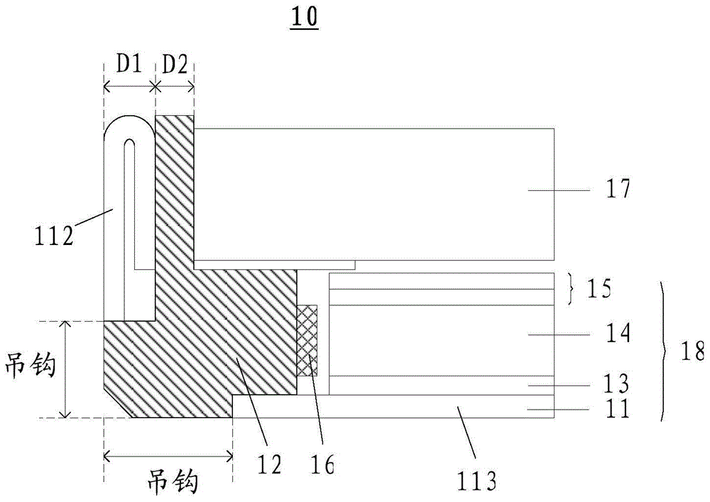
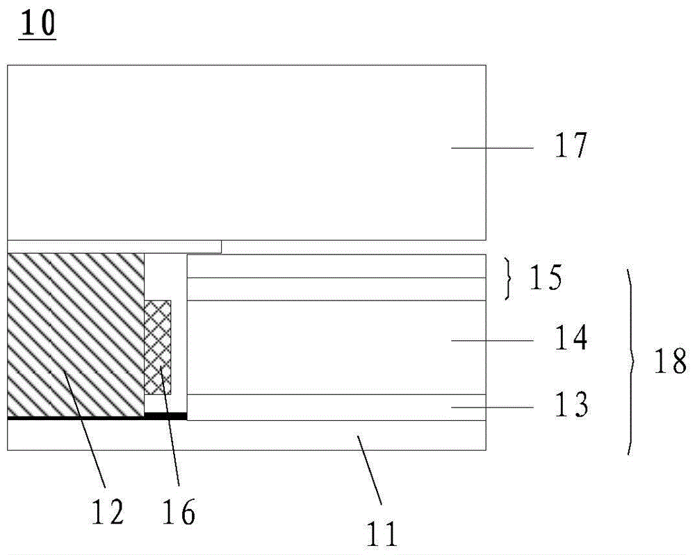
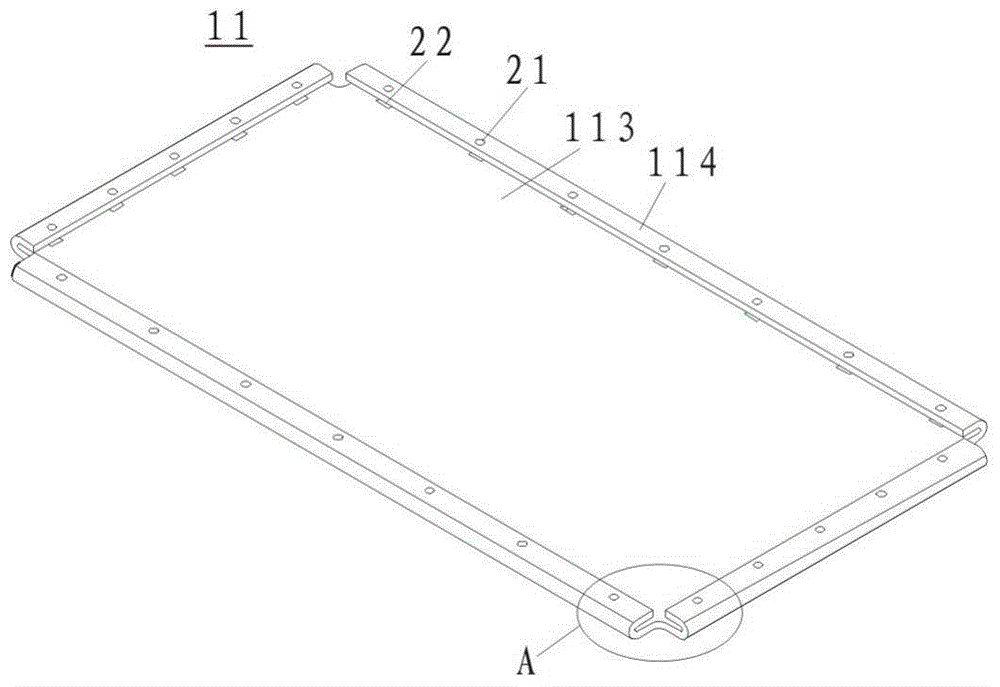
[0050] The embodiment of the present invention provides a backboard 11, including a...


PUM


Abstract

The invention provides a backboard, a backboard component and a manufacturing method thereof as well as a backlight module and relates to the technical field of display. The backboard can be used for solving the solving the problem that an existing backboard can not meet the requirements on strength and narrow frame application at the same time when combined with a glue frame. The backboard comprises a bottom plate and at least two reinforced plates respectively connected with two opposite sides of the bottom plate, wherein the reinforced plates cover the edges of the bottom plate and are provided with multiple first through holes; the bottom plate is provided with multiple second through holes; part of the second through holes is shielded by the reinforced plates, and the second through holes are communicated with the first through holes.

Description

technical field [0001] The invention relates to the field of display technology, in particular to a backplane, a backplane assembly, a manufacturing method thereof, and a backlight module. Background technique [0002] The liquid crystal display device has many advantages such as a thin body, power saving, and no radiation, and is widely used. [0003] figure 1 Shown is a partial schematic diagram of an existing liquid crystal display device. The liquid crystal display device 10 includes a backlight module 18 and a liquid crystal panel 17 arranged on the backlight module 18, and the backlight module 18 generally includes a backplane 11, a plastic frame 12. LED lights 16 , reflective sheet 13 , light guide plate 14 and prism sheet 15 arranged on the back plate 11 . Wherein, the backplane 11 mainly provides the supporting force of the reflection sheet 13 and the light guide plate 14 arranged on the backplane 11, and the plastic frame 12 is mainly used for connecting the back...

Claims


Application Information

Patent Timeline
IPC IPC(8): G02F1/13357
CPCG02F1/133608
Inventor 金文峰翟明刘宇飞魏长春姜太声金亨奎
Owner BOE TECH GRP CO LTD
Why Eureka
Try Eureka