Heat radiator

A technology of a heat sink and a heat sink set, which is applied in cooling/ventilation/heating transformation, electrical components, electric solid devices, etc., can solve the problems of heat pipe deformation and affect the heat dissipation efficiency of the heat sink, so as to reduce pressure and avoid pressure. Deformation, the effect of ensuring heat dissipation efficiency

Inactive Publication Date: 2009-12-09
FU ZHUN PRECISION IND SHENZHEN +1
View PDF0 Cites 3 Cited by
  • Summary
  • Abstract
  • Description
  • Claims
  • Application Information

AI Technical Summary

Problems solved by technology

[0003] The traditional tower cooling device stacks a number of cooling fins arranged in parallel on the base through heat pipes, and a fan is installed on one side of the cooling fins. The cooling fins and the fan are only supported by

Method used


Image

  • Heat radiator
  • Heat radiator
  • Heat radiator

Examples


Embodiment Construction

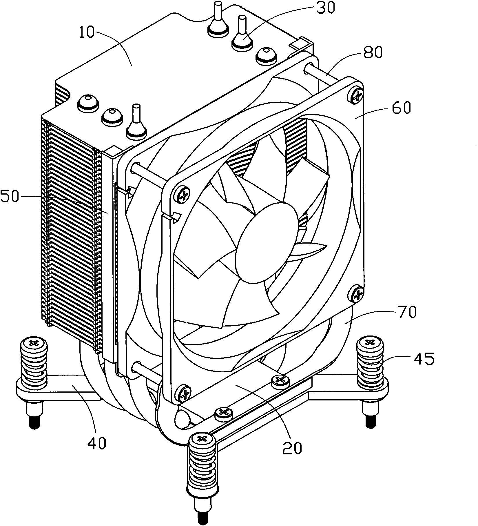
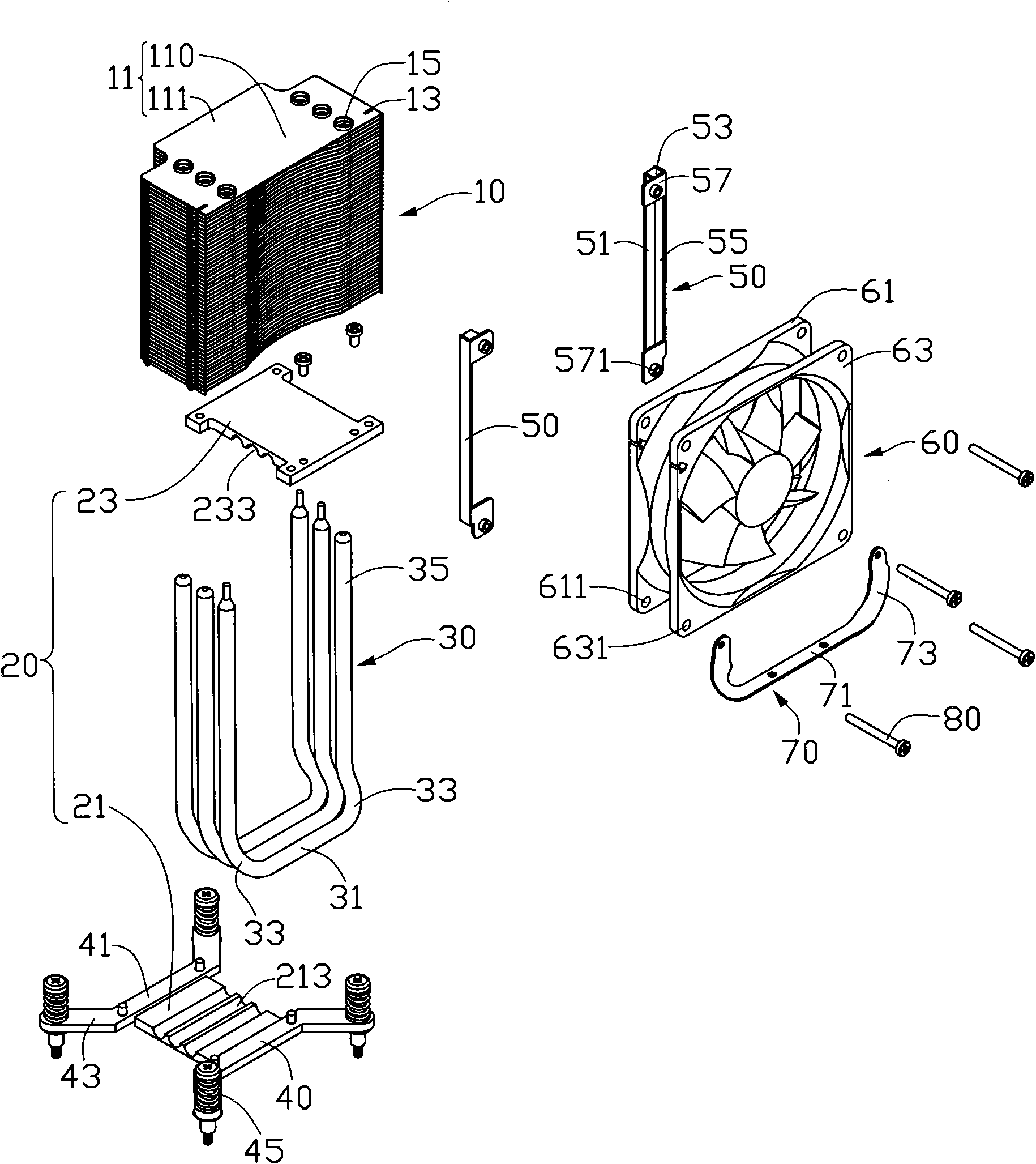
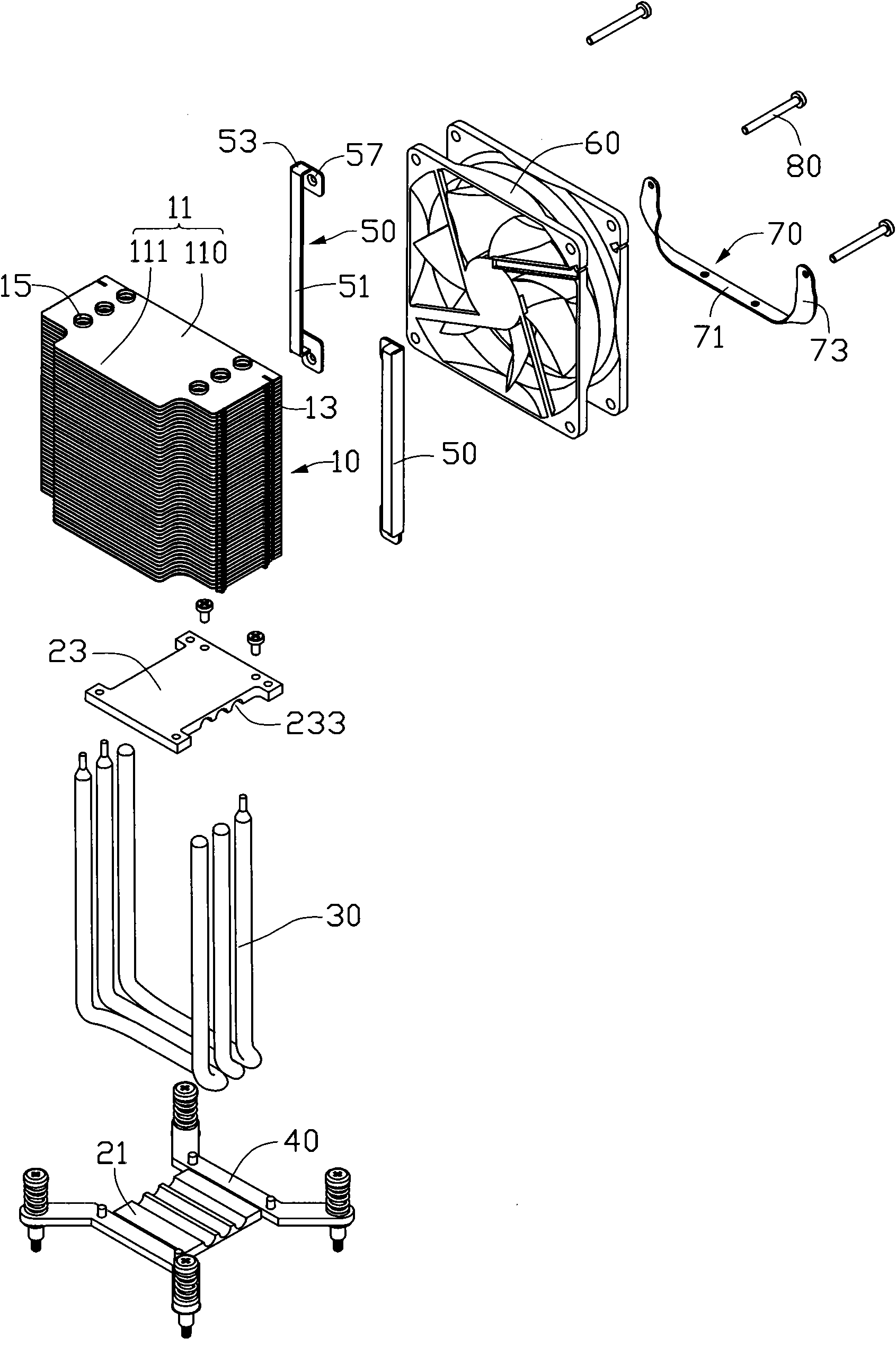
[0011] Such as figure 1 and figure 2 As shown, the heat dissipation device of the present invention is used to dissipate heat from a heat-generating electronic component (not shown) fixed on a circuit board (not shown). The heat dissipation device includes a base plate 20 in contact with the heat-generating electronic component, a heat sink set 10 above the base plate 20, three heat pipes 30 connecting the heat sink set 10 and the base plate 20, and two fans installed on one side of the heat sink set 10. The fixing frame 50 , a fan 60 connected with the fan fixing frame 50 , a supporting frame 70 connecting the fan 60 and the substrate 20 , and two fixing frames 40 fixing the substrate 20 on the circuit board.

[0012] The three heat pipes 30 are arranged at intervals and are all U-shaped. Each heat pipe 30 includes a straight evaporating section 31 , two connecting sections 33 bent and extending from opposite sides of the evaporating section 31 , and two condensing section...


PUM


Abstract

The invention relates to a heat radiator for radiating the heat of an electronic component fixed on a circuit board. The heat radiator comprises a base board, a cooling fin group, a heat pipe and a fan, wherein the cooling fin group is arranged above the base board, the heat pipe is used for connecting the base board and the cooling fin group, and the fan is arranged on one side of the cooling fin group; the heat radiator also comprises a supporting frame comprising a fixing part and two supporting arms, the fixing part is fixed on the base board, the two supporting arms extend from the fixing part, and the two supporting arms are fixedly connected with the fan so as to supporting the fan. Compared with the prior art, the fan of the heat radiator is supported by the supporting frame, thereby the pressure on the heat pipe from the fan is reduced, the press deformation of the heat pipe is avoided, and the heat radiating efficiency of the heat radiator is ensured.

Description

technical field [0001] The invention relates to a cooling device, in particular to a cooling device for cooling electronic components. Background technique [0002] As we all know, electronic components such as central processing units generate a lot of heat during operation. In order to prevent the temperature of the electronic component from rising due to the accumulation of heat and thus cause its operation to be unstable, the electronic component usually needs to be equipped with a heat dissipation device to assist in heat dissipation. [0003] The traditional tower cooling device stacks a number of cooling fins arranged in parallel on the base through heat pipes, and a fan is installed on one side of the cooling fins. The cooling fins and the fan are only supported by the heat pipes. When the radiator works for a period of time Or during transportation, due to the gravity of the fan and frequent vibrations, the heat pipe is deformed and the heat dissipation efficiency ...

Claims


Application Information

Patent Timeline
IPC IPC(8): H05K7/20H01L23/34H01L23/40H01L23/427H01L23/467
Inventor 吴宜强陈俊吉
Owner FU ZHUN PRECISION IND SHENZHEN
Why Eureka
Try Eureka