Automatic container lockhole identifying-positioning method and system

An automatic identification and positioning method technology, applied in character and pattern recognition, image data processing, instruments, etc., can solve problems such as improvement, cost increase, cost doubling, etc., to reduce cost, improve accuracy, and improve function scalability. Effect

Inactive Publication Date: 2015-11-18
SHANGHAI ZHENHUA HEAVY IND
View PDF4 Cites 13 Cited by
  • Summary
  • Abstract
  • Description
  • Claims
  • Application Information

AI Technical Summary

Problems solved by technology

The key technology of the existing laser scanning positioning system is mastered by foreign manufacturers, and the price is very expensive. Many large-scale mechanical laser scanning technologies need to install multiple devices to realize the function, and the cost doubles.
For example, the cranemate-based laser sensor positioning system will greatly increase the cost due to the limitation of the installation location

Method used


Image

  • Automatic container lockhole identifying-positioning method and system
  • Automatic container lockhole identifying-positioning method and system

Examples


Embodiment Construction

[0028] The above-mentioned features and advantages of the present invention can be better understood after reading the detailed description of the embodiments of the present disclosure in conjunction with the following drawings. In the drawings, components are not necessarily drawn to scale, and components with similar related properties or characteristics may have the same or similar reference numerals.

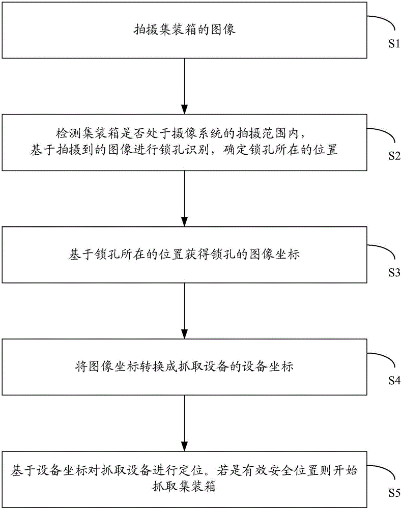
[0029] figure 1 The flow chart of a preferred embodiment of the container lockhole automatic identification and positioning method of the present invention is shown, please refer to figure 1 , the following is a detailed description of each step of the method of this embodiment.

[0030] Step S1: Take an image of the container.

[0031] Preferably, the camera or the binocular system of the camera is calibrated before shooting.

[0032] Step S2: Carry out keyhole recognition based on the captured image, and determine the location of the keyhole.

[0033] Preferably, befor...


PUM


Abstract

The invention discloses an automatic container lockhole identifying-positioning method and system. A camera collects an image, a container lockhole in the image is positioned, a device coordinate system is obtained and then transmitted to a controller for subsequent control processing, a controller positions the device according to a given position, and a container is grabbed if the position is effective and safe. The method and system can improve the positioning precision, reduce the positioning cost and can expand functions according to requirements.

Description

technical field [0001] The invention relates to a technology for identifying and locating a lock hole of a container, in particular to a method and a system for automatically identifying and locating a container lock hole by using an industrial camera. Background technique [0002] In the process of grabbing the container, it is necessary to locate the keyhole of the container. The current positioning adopts the technology of laser scanning positioning. The key technologies of existing laser scanning positioning systems are all mastered by foreign manufacturers, and the price is very expensive. Many large-scale mechanical laser scanning technologies need to install multiple devices to realize their functions, and the cost doubles. For example, the cranemate-based laser sensor positioning system will greatly increase the cost due to the limitation of the installation location. [0003] Therefore, the industry urgently needs to reduce the positioning cost of the container key...

Claims


Application Information

Patent Timeline
Patent Type & Authority Applications(China)
IPC IPC(8): G06K9/00G06T7/00
CPCG06V40/13
Inventor 张瑜杰张洪波
Owner SHANGHAI ZHENHUA HEAVY IND
Why Eureka
Try Eureka