Tube-type solid oxide fuel cell monocell and preparation method thereof

A solid oxide and fuel cell technology, applied in solid electrolyte fuel cells, fuel cells, fuel cell components, etc., can solve problems such as high temperature sealing difficulties, and achieve the effects of sealing and sintering, easy assembly and construction

Inactive Publication Date: 2015-11-18
TIANJIN UNIV
4 Cites 0 Cited by

AI-Extracted Technical Summary

Problems solved by technology

The invention overcomes the deficiencies in the prior art, adopts the ceramic sealing and sintering method to seal and sinter all the parts of...

Method used

As shown in accompanying drawing 4, the upper joint of fuel cell power generation pipe body is made up of cylinder wall and cylinder cavity, and lower opening is consistent with the size of the upper end of fuel cell power generation pipe body, and upper opening is larger than lower opening, to form inverted "convex" The structure, that is, the upper joint of the fuel cell power generation tube is a cylindrical structure with variable diameter; the lower joint of the fuel cell power generation tube can adopt the same structure as shown in Figure 3, and the upper opening is consistent with the size of the lower end of the fuel cell power generation tube. The lower opening is larger than the upper opening. Choose a cylindrical structure with variable diameter to facilitate the connection of the upper and lower joints with the anode inlet and outlet pipes. At the same time, in order to facilitate sealing, grooves or slots are provided at the interface between the upper joint of the fuel cell power generation tube body and the fuel cell power generation tube ...

Abstract

The invention discloses a tube-type solid oxide fuel cell monocell and a preparation method thereof. In the tube-type monocell, a fuel cell generation tube body is arranged in a cathode shell, a cathode air inlet tube and a cathode air outlet tube are arranged between the cathode shell and the fuel cell generation tube body, an upper connector of the fuel cell generation tube body is arranged at the upper end of the fuel cell generation tube body, a lower connector of the fuel cell generation tube body is arranged at the lower end of the fuel cell generation tube body, and a cathode binding post and an anode binding post are arranged at a position where the fuel cell generation tube body and the cathode shell are in contact. With the adoption of a ceramic sealing sintering technique, all components of the fuel cell monocell are sealed and sintered to form an integrated ceramic structure, the problem of difficulty in sealing of all components of the solid oxide fuel cell in a high-temperature working condition is avoided, and the solid oxide fuel cell is further easy to assemble and build.

Application Domain

Final product manufactureSolid electrolyte fuel cells +1

Technology Topic

EngineeringOxide +6

Image

  • Tube-type solid oxide fuel cell monocell and preparation method thereof
  • Tube-type solid oxide fuel cell monocell and preparation method thereof
  • Tube-type solid oxide fuel cell monocell and preparation method thereof

Examples

  • Experimental program(1)

Example Embodiment

[0024] The technical solutions of the present invention will be further described below through specific examples.
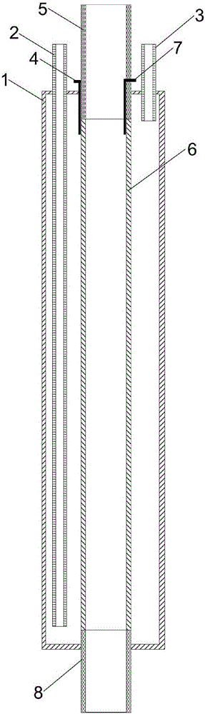
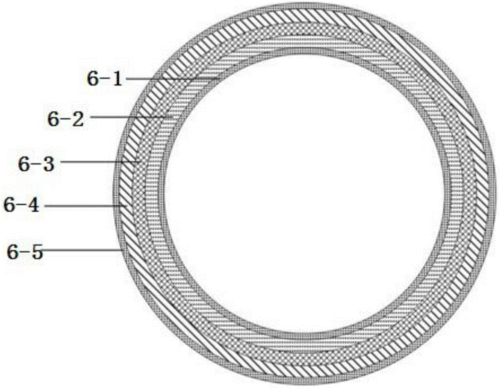
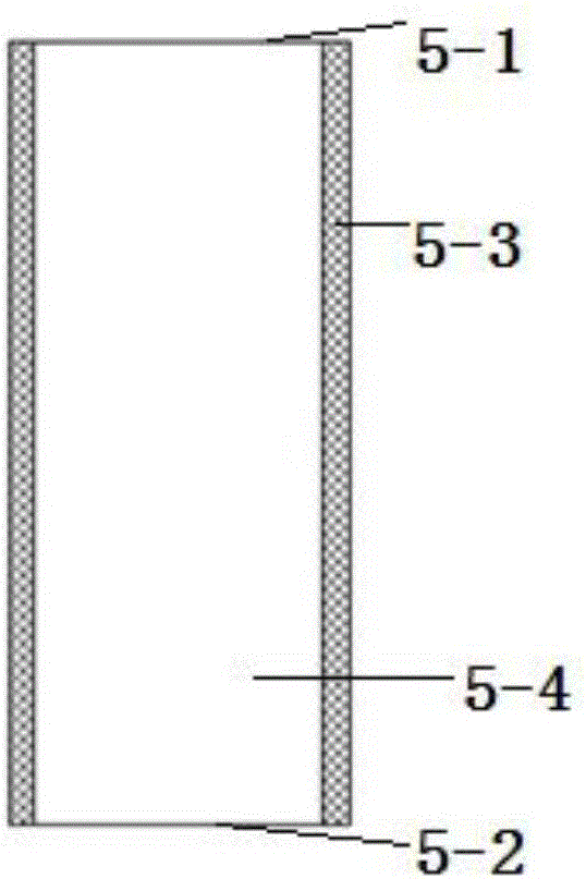
[0025] like figure 1 As shown, a single tubular solid oxide fuel cell, 1 is the cathode shell, 2 is the cathode air intake pipe, 3 is the cathode air outlet pipe, 4 is the cathode terminal, 5 is the connector on the fuel cell power generation tube body, and 6 is the The fuel cell power generation tube body, 7 is the anode terminal, and 8 is the lower joint of the fuel cell power generation tube body, wherein:
[0026]A fuel cell power generation pipe is arranged in the cathode casing, the length of the fuel cell power generation pipe is shorter than the cathode casing, a cathode air intake pipe and a cathode gas outlet pipe are arranged between the cathode casing and the fuel cell power generation pipe, and one end of the cathode air intake pipe is arranged at On the outside of the cathode casing, the other end of the cathode air intake pipe extends near the bottom of the cathode casing, one end of the cathode gas outlet pipe is arranged outside the cathode casing, and the other end of the cathode gas outlet pipe extends near the top of the cathode casing to generate electricity in the fuel cell. The upper end of the tube body is provided with the upper joint of the fuel cell power generation tube body, the lower end of the fuel cell power generation tube body is provided with the lower joint of the fuel cell power generation tube body, and the cathode terminal is set at the position where the upper joint of the fuel cell power generation tube body contacts with the cathode shell and the anode terminal, one end of the cathode terminal is set on the outside of the contact position between the joint on the fuel cell power generation tube body and the fuel cell power generation tube body, and one end of the cathode terminal passes through the cathode casing; one end of the anode terminal is set on the fuel cell power generation tube. The inner side of the position where the upper joint of the tube body is in contact with the power generation tube body of the fuel cell, the other end of the anode terminal passes through the upper joint of the power generation tube body of the fuel cell.
[0027] Specifically, one end of the cathode terminal is arranged on the outer surface of the upper opening of the fuel cell power generation tube, and the body of the cathode terminal extends along the outer surface of the fuel cell power generation tube and the fuel cell power generation tube in contact with the fuel cell power generation tube. The outer surface of the upper joint is arranged, and the other end of the cathode terminal passes through the cathode casing; one end of the anode terminal is arranged on the inner surface of the upper opening of the fuel cell power generation tube body, and the body of the anode terminal extends along the inner surface of the fuel cell power generation tube and is connected to the inner surface of the fuel cell power generation tube. The inner surface of the upper joint of the fuel cell power generation tube which is in contact with the fuel cell power generation tube is arranged, and the other end of the anode terminal passes through the upper joint of the fuel cell power generation tube.
[0028] like figure 2 As shown, 6-1 is the fuel cell anode current collector layer, 6-2 is the fuel cell anode layer, 6-3 is the fuel cell electrolyte layer, 6-4 is the fuel cell cathode, and 6-5 is the fuel cell cathode current collector layer ,in
[0029] The fuel cell power generation tube is composed of fuel cell anode current collecting layer, fuel cell anode layer, fuel cell electrolyte layer, fuel cell cathode and fuel cell cathode current collecting layer, fuel cell anode current collecting layer, fuel cell anode layer, fuel cell electrolyte Layers, fuel cell cathodes and fuel cell cathode current collecting layers are sequentially arranged in concentric circles from inside to outside so that the fuel cell power generation tube as a whole has a cylindrical shape.
[0030] The fuel cell anode current collecting layer and the fuel cell cathode current collecting layer adopt metallic platinum or other metals or alloy materials with high electrical conductivity that are stable under the fuel cell atmosphere. The fuel cell anode layer, the fuel cell electrolyte layer, and the fuel cell cathode are respectively selected from the battery anode material, electrolyte material, and battery cathode material in the fuel cell domain.
[0031] The cathode casing of the fuel cell, the cathode inlet pipe, the cathode outlet pipe, the upper joint of the fuel cell power generation tube, and the lower joint of the fuel cell power generation tube are all made of ceramic materials, and the ceramic material is alumina, zirconia, mullite or cordierite. one or more of.
[0032] The cathode terminal and the anode terminal are made of metal platinum or other metals or alloy materials that are stable in the atmosphere of the fuel cell and have high conductivity.
[0033] In the entire fuel cell single cell, all parts (cathode casing, cathode air intake pipe, cathode air outlet pipe, cathode terminal, upper joint of fuel cell power generation tube, fuel cell power generation tube, anode terminal and fuel cell power generation tube under Joints) are sealed and bonded together with a high-temperature ceramic sealant. Specifically, each component (ceramic component) is designed and prepared separately, and then each is sealed, bonded, and sintered with a high-temperature ceramic sealant. The lower end of the fuel cell power generation tube body is sealed, bonded and sintered with the lower joint of the fuel cell power generation tube body with high-temperature ceramic glue, and the upper end of the fuel cell power generation tube body is sealed, bonded and sintered with the upper joint of the fuel cell power generation tube body with high-temperature ceramic glue. The upper joint of the fuel cell power generation tube body, the fuel cell power generation tube body and the lower joint of the fuel cell power generation tube body form the anode cavity, and the cathode terminal and the anode terminal are pressed figure 1 shown fixed to the anode cavity. The lower opening of the lower joint of the fuel cell power generation tube serves as the anode air inlet, and the upper opening of the upper joint of the fuel cell power generation tube serves as the anode gas outlet. Fuel cell cathode casing, cathode inlet pipe and cathode outlet pipe according to figure 1 As shown, the cathode cavity is obtained by sealing, bonding and sintering with a high-temperature ceramic sealant. Fuel cell cathode cavity and anode cavity according to figure 1 As shown, the sealed bonding sintering results in sintered solid oxide fuel cells.
[0034] as attached image 3 As shown, the upper joint of the fuel cell power generation tube body is in the shape of a cylinder with a rectangular cross-section. It is used to connect with the upper end of the fuel cell power generation tube, and the upper opening is used as an anode gas outlet. The lower joint of the fuel cell power generation tube can be used with the attached image 3 In the same structure as shown, the upper opening is connected to the lower end of the fuel cell power generation tube, and the lower opening is used as an anode air inlet.
[0035] as attached Figure 4 As shown, the upper joint of the fuel cell power generation tube is composed of the cylinder wall and the cylinder cavity, the lower opening is the same size as the upper end of the fuel cell power generation tube, and the upper opening is larger than the lower opening to form an inverted "convex" structure, that is, the fuel cell power generation tube The joint on the body is a cylindrical structure with variable diameter; the joint under the body of the fuel cell power generation tube can be image 3 As shown in the same structure, the size of the upper opening is the same as that of the lower end of the fuel cell power generation tube, and the lower opening is larger than the upper opening. Choose a cylindrical structure with variable diameter to facilitate the connection of the upper and lower joints with the anode inlet and outlet pipes. At the same time, in order to facilitate sealing, grooves or slots are provided at the interface between the upper joint of the fuel cell power generation tube body and the fuel cell power generation tube body, and at the interface between the lower joint of the fuel cell power generation tube body and the fuel cell power generation tube body.
[0036] Due to the temperature rise at the anode gas outlet during the continuous reaction process, a cooling device is installed outside the joint on the fuel cell power generation tube, such as the attached Figure 5 (Schematic diagram of external structure) and 6 (Schematic diagram of cross-section), a cooling jacket is arranged outside the joint on the fuel cell power generation tube body, and a cooling medium inlet and a cooling medium outlet are arranged on the cooling jacket; if attached Figure 7 As shown in (Schematic Diagram of External Structure) and 8 (Schematic Diagram of Section), a cooling coil is arranged on the outer side of the upper joint of the fuel cell power generation tube body, and a cooling medium inlet and a cooling medium outlet are provided.
[0037] The beneficial effects of the invention are: the two ends of the fuel cell power generation tube are ceramic interfaces, and the ceramic interfaces can be designed according to the shape of the interface of the external gas circuit. The cathode casing, cathode inlet pipe, cathode outlet pipe, anode cavity, ceramic interface at both ends, power generation tube body and electrodes of the fuel cell single cell are sintered into one by the method of ceramic sintering and sealing, except for a small amount of metal parts, The rest of the components are made of ceramic materials with close thermal expansion coefficients, which is conducive to sealing and sintering. The ceramic structure of the single fuel cell sintered into one avoids the problem of difficult sealing of solid oxide fuel cells under high temperature working conditions, making solid oxidation Further assembly and construction of biofuel cells is easier.
[0038] The present invention has been described as an example above, and it should be noted that, without departing from the core of the present invention, any simple deformation, modification or other equivalent replacements that can be made by those skilled in the art without creative labor all fall within the scope of this invention. protection scope of the invention.

PUM

no PUM

Description & Claims & Application Information

We can also present the details of the Description, Claims and Application information to help users get a comprehensive understanding of the technical details of the patent, such as background art, summary of invention, brief description of drawings, description of embodiments, and other original content. On the other hand, users can also determine the specific scope of protection of the technology through the list of claims; as well as understand the changes in the life cycle of the technology with the presentation of the patent timeline. Login to view more.
Why Eureka
Try Eureka