Control system for hydraulic system and method for recovering energy and leveling hydraulic system loads

A technology of pressure and summation, which is applied in the field of hydraulic systems and can solve problems such as energy loss

Inactive Publication Date: 2015-11-18
EATON INTELLIGENT POWER LIMITED
View PDF6 Cites 8 Cited by
  • Summary
  • Abstract
  • Description
  • Claims
  • Application Information

AI Technical Summary

Problems solved by technology

Due to throttling, there is often a la...

Method used


Image

  • Control system for hydraulic system and method for recovering energy and leveling hydraulic system loads
  • Control system for hydraulic system and method for recovering energy and leveling hydraulic system loads
  • Control system for hydraulic system and method for recovering energy and leveling hydraulic system loads

Examples


Embodiment Construction

[0031] Aspects of the invention illustrated in the accompanying drawings will now be described in detail. Wherever possible, the same reference numbers will be used throughout the drawings to refer to the same or like structures.

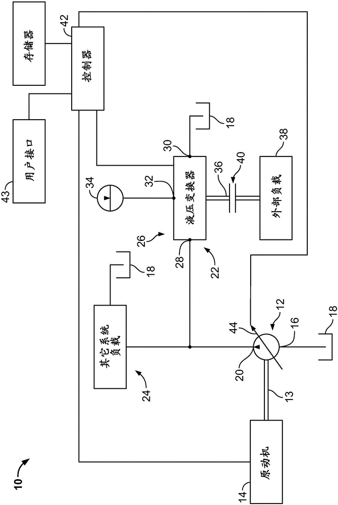
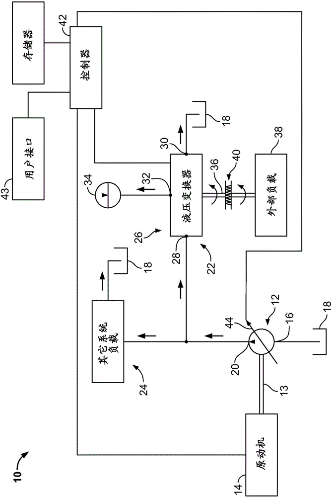
[0032] figure 1 A system 10 in accordance with the principles of the present invention is shown. System 10 includes a variable displacement pump 12 driven by a prime mover 14 (eg, a diesel engine, spark ignition engine, electric motor, or other power source). The variable displacement pump 12 includes an inlet 16 that draws low pressure hydraulic fluid from a tank 18 (ie, a low pressure reservoir). The variable displacement pump 12 also includes an outlet 20 through which high pressure hydraulic fluid exits. Outlet 20 is preferably fluidly coupled to a plurality of different workload circuits. For example, outlet 20 is shown coupled to a first load circuit 22 and a second load circuit 24 . The first load circuit 22 includes a hydraulic transduc...


PUM


Abstract

A control system for a hydraulic system including an accumulator and a hydraulic transformer coordinates flow sharing within the hydraulic system. The hydraulic transformer includes first and second variable displacement pump/motor units mounted on a rotatable shaft. The rotatable shaft has an end adapted for connection to a first external load. The first variable displacement pump/motor unit includes a first side that fluidly connects to a pump and a second side that fluidly connects to a tank. The second variable displacement pump/motor unit includes a first side that fluidly connects to the accumulator and a second side that fluidly connects with the tank. A second external load may be hydraulically connected to the hydraulic system. Energy may be transferred to/from the pump, the accumulator, the first external load, and/or the second external load, as directed by the control system.

Description

[0001] Cross References to Related Applications [0002] This application was filed as a PCT International Patent Application on December 17, 2013, and claims priority to U.S. Patent Application Serial No. 61 / 739,508, filed December 19, 2012, the disclosure of which is incorporated by reference in its entirety way incorporated into this article. Background technique [0003] Mobile machinery such as excavators typically include a hydraulic system with hydraulically driven linear and rotary actuation for powering various moving machine components such as linkages, tracks, swivel joints, etc. device. Typically, linear actuators include hydraulic cylinders and rotary actuators include hydraulic motors. By manipulating the user interface of the machine control system, a machine operator can control the motion of various machine components. [0004] A typical mobile machine includes a prime mover (eg, diesel engine, spark ignition engine, electric motor, etc.) serving as the ove...

Claims


Application Information

Patent Timeline
IPC IPC(8): F15B21/14E02F9/22
CPCE02F9/2217E02F9/2075E02F9/2232E02F9/2296F15B21/14F15B2211/20546F15B2211/20569F15B2211/212F15B2211/214F15B2211/2654F15B2211/3059F15B2211/6306F15B2211/633F15B2211/6336F15B2211/6346F15B2211/6652F15B2211/7058F15B2211/7135F15B2211/761F15B2211/88Y10T137/0379
Inventor 王萌A·H·雅各达C·A·拉利许D·皮亚博格卡恩P·W·丹泽尔V·马胡尔卡
Owner EATON INTELLIGENT POWER LIMITED
Why Eureka
Try Eureka