Novel centrifugal machine static balancing device

A centrifuge and balancing technology, applied in centrifuges and other directions, can solve the problems of increased labor and material costs, uneven force on the synchronous belt, complicated operation of the synchronous belt, etc. Effect

Active Publication Date: 2015-11-25
GENERAL ENG RES INST CHINA ACAD OF ENG PHYSICS
View PDF7 Cites 6 Cited by
  • Summary
  • Abstract
  • Description
  • Claims
  • Application Information

AI Technical Summary

Problems solved by technology

This electric structure greatly improves the accuracy of trimming and reduces the complexity of operation. However, this structure uses a long annular synchronous belt to drive two nuts at the same time, which will easily cause uneven force on the synchronous belt and increase the The probability of damage to the synchronous belt requires regular replacement of the synchronous belt, and the operation of replacing a longer synchronous belt is more complicated, which increases labor and material costs; in addition, because the lead screw of the synchronous belt moving trim structure is the tensile force of the circular section of the arm belt, so it can only be used in centrifuges with circular section of the pull belt of the rotating arm, so the application range is limited

Method used


Image

  • Novel centrifugal machine static balancing device
  • Novel centrifugal machine static balancing device
  • Novel centrifugal machine static balancing device

Examples


Embodiment Construction

[0021] The present invention will be further explained below in conjunction with the drawings:

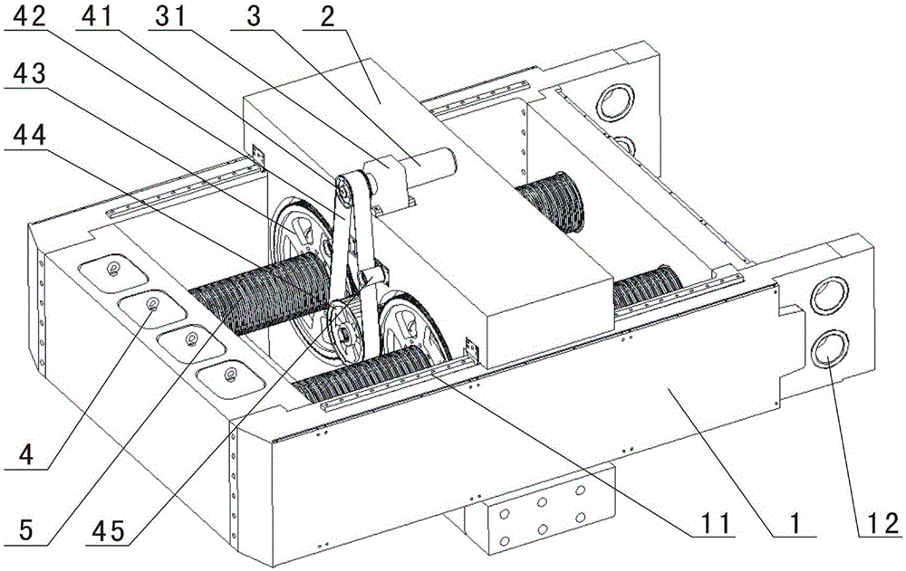
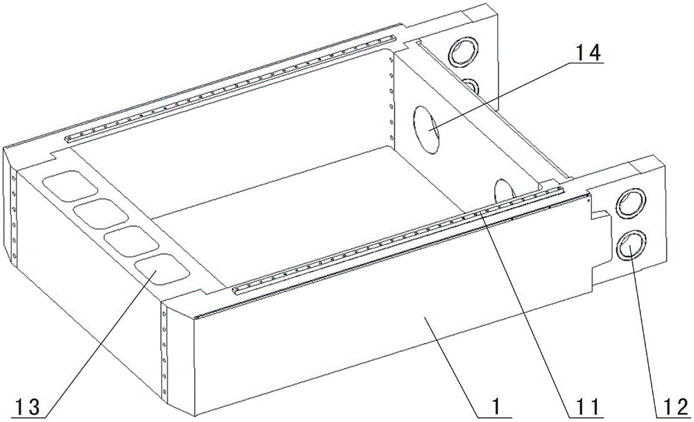
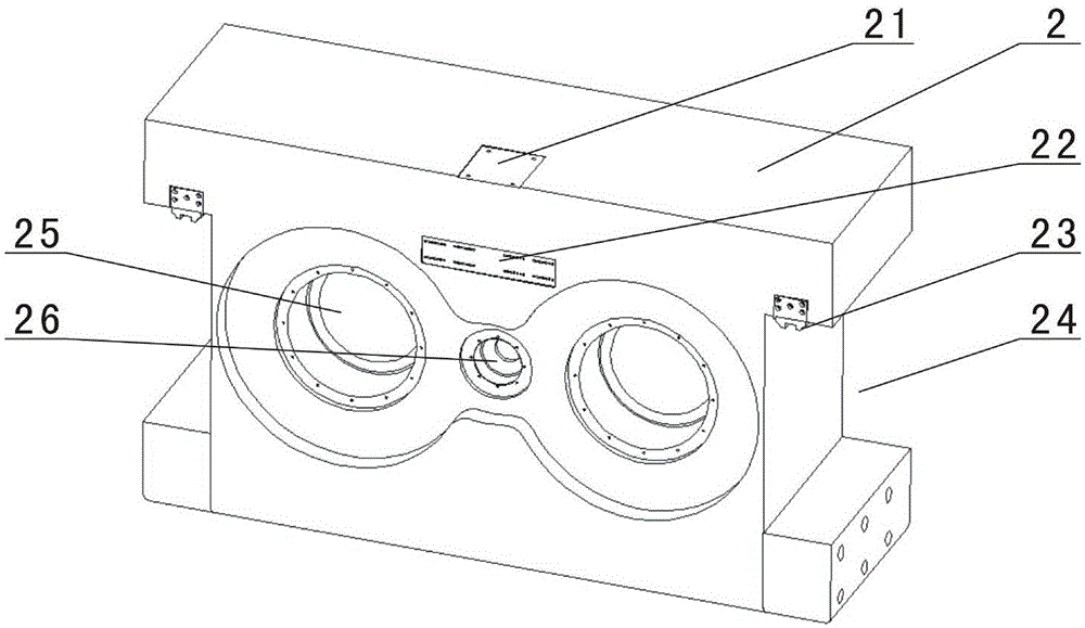
[0022] Such as Figure 1-Figure 4 As shown, the static balancing device of the novel centrifuge of the present invention includes a balancing frame 1, a lead screw 5, a moving counterweight 2, a motor 3, a rotating transmission device and a walking nut 48. The first end of the balancing frame 1 is provided with The rotating arm of the centrifuge (not shown) is connected to the connecting hole 12, the second end of the trim frame 1 is provided with a fixed weight hole 13, and the fixed weight hole 13 is installed with a fixed weight 4, and the balance frame 1 Two rails 11 are respectively provided on the upper surfaces of both sides and the two rails 11 are parallel to each other. The two ends of the movable counterweight 2 are respectively installed on the two guide rails 11 and can move, and the motor 3 is installed on the movable counterweight 2; The weight 2 is provided with a cen...


PUM


Abstract

The invention discloses a novel centrifugal machine static balancing device. The novel centrifugal machine static balancing device comprises a balancing frame, a lead screw, a movable balancing weight, a motor, a rotary transmission device and a traveling nut. A connecting hole is formed in the first end of the balancing frame, and a fixed balancing weight is installed at the second end of the balancing frame. Two guide rails are arranged on the upper surfaces of the two sides of the balancing frame in parallel respectively. The two ends of the movable balancing weight are installed on the two guide rails respectively and can be moved. The motor is installed on the movable balancing weight. A rotary shaft of the motor is connected with the input end of the rotary transmission device. The output end of the rotary transmission device is connected with the traveling nut. The lead screw is sleeved with the traveling nut. The two ends of the lead screw are fixedly installed at the two ends of the balancing frame respectively. Through the combination of the movable balancing weight and the fixed balancing weight, the novel centrifugal machine static balancing device has the advantages that machining is easy due to modular design, the balancing range is wide, the application range is wide, and operation is easy.

Description

Technical field [0001] The invention relates to a centrifuge static trimming device, in particular to a novel centrifuge static trimming device with modular design, large trim range and simple operation. Background technique [0002] As an important part of the centrifuge, the static trim device directly affects the stability, safety and service life of the centrifuge. At present, some domestic centrifuges adopt a long and short arm structure. The long end is used to install the test piece, and the short end is used to install a large mass counterweight to ensure equal torque at both ends. The short arm and counterweight are static trim devices. Most centrifuges of this type of long and short arm structure adopt a fixed counterweight trim method, that is, based on the principle of torque balance, a specific mass of counterweight is installed at the end of the short arm to achieve trimming. Due to the limited specifications of the counterweights, the combination of the counterwei...

Claims


Application Information

Patent Timeline
Patent Type & Authority Applications(China)
IPC IPC(8): B04B9/14
Inventor 陈磊洪建忠张建全蒋春梅赵世鹏成永博李心耀
Owner GENERAL ENG RES INST CHINA ACAD OF ENG PHYSICS
Why Eureka
Try Eureka