Connecting rod drive type punching mechanism

A technology of connecting rod drive and drive end, applied in metal processing and other directions, can solve the problem of low punching efficiency, and achieve the effects of easy promotion and use, flexible action, low production and maintenance costs

Inactive Publication Date: 2015-11-25
GUANGXI UNIV
View PDF6 Cites 3 Cited by
  • Summary
  • Abstract
  • Description
  • Claims
  • Application Information

AI Technical Summary

Problems solved by technology

[0005] The object of the present invention is to provide a link-driven punching mechanism,

Method used


Image

  • Connecting rod drive type punching mechanism
  • Connecting rod drive type punching mechanism

Examples


Example Embodiment

[0017] The specific embodiments of the present invention will be described in detail below with reference to the accompanying drawings, but it should be understood that the protection scope of the present invention is not limited by the specific embodiments.

[0018] Unless expressly stated otherwise, throughout the specification and claims, the term "comprising" or its conjugations such as "comprising" or "comprising" and the like will be understood to include the stated elements or components, and Other elements or other components are not excluded.

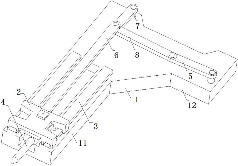
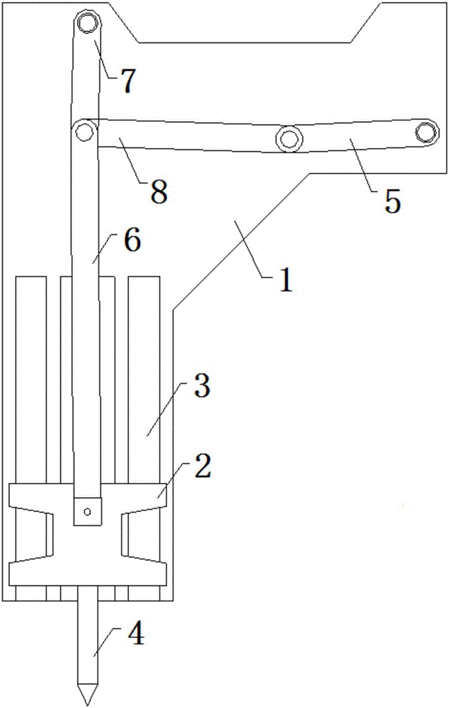
[0019] like Figure 1 to Figure 2 As shown, the connecting rod-driven punching mechanism according to the specific embodiment of the present invention includes: a main board 1, a slider 2, a punching needle 4, a sliding rod 6, an ejector rod 7, a pull rod 8 and a driving device; A driving end 12 and a punching end 11 are provided, and the driving end 12 is located to the right of the punching end 11; the punching needle 4 is s...


PUM


Abstract

The invention discloses a connecting rod drive type punching mechanism. The connecting rod drive type punching mechanism comprises a main plate, a punching needle, a crank, a slide rod, an ejector rod, a pull rod and a drive device. The main plate is provided with a drive end and a punching end. The punching needle is arranged at the punching end through a slide block in a vertical sliding manner. One end of the crank is hinged to the drive end. One end of the slide rod is hinged to the slide block. One end of the ejector rod is hinged to the upper portion of the slide rod. One end of the pull rod is hinged to the other end of the crank. The other end of the slide rod, the other end of the ejector rod and the other end of the pull rod are hinged to the same point. The drive device is connected with the crank so as to drive the crank to rotate. When the crank rotates upwards by a half circle, the crank drives the pull rod to drive the slide rod to move upwards through the same hinge point. When the crank rotates downwards by a half circle, the crank drives the pull rod to drive the slide rod to move downwards through the same hinge point. The connecting rod drive type punching mechanism can overcome the defect that an existing punching machine is low in punching efficiency.

Description

technical field [0001] The invention relates to the field of punching mechanisms, in particular to a connecting rod-driven punching mechanism. Background technique [0002] The punching machine is used for the processing of holes for specific materials. It usually includes an upright fuselage and a machine head set on the top of the fuselage and extending horizontally. The side of the punching machine corresponding to the outer end of the machine head is the punching end. The automatic punching machine is one of the existing punching machines, which can be used for automatic punching of sheet materials. However, in the traditional setting of isolated punching machines, on the one hand, a single punching machine completes the punching of the entire material before proceeding to the next material, and the material is manually transferred between the punching machines, resulting in low work efficiency and high labor costs; On the one hand, for materials whose width exceeds the...

Claims


Application Information

Patent Timeline
IPC IPC(8): B26F1/24B26D5/14B26D7/26
Inventor 李海波耿葵花王潇马小波
Owner GUANGXI UNIV
Why Eureka
Try Eureka