
A Flutter Model of Aircraft Missile System

A flutter model and missile technology, applied in the field of aviation test, can solve the problems of inconvenient adjustment of stiffness, difficult identification of pitch and yaw mode coupling, etc., and achieve the effect of saving test funds and time

Active Publication Date: 2017-02-01
XIAN AIRCRAFT DESIGN INST OF AVIATION IND OF CHINA
View PDF6 Cites 0 Cited by
  • Summary
  • Abstract
  • Description
  • Claims
  • Application Information

AI Technical Summary

Problems solved by technology

[0003] The purpose of the present invention is to provide a flutter model of an aircraft missile system to solve the problems that the pitch and yaw modal coupling is difficult to identify and the stiffness adjustment is inconvenient in the current flutter model

Method used


Image

  • A Flutter Model of Aircraft Missile System
  • A Flutter Model of Aircraft Missile System

Examples


Embodiment Construction

[0022] Reference will now be made in detail to the exemplary embodiments, examples of which are illustrated in the accompanying drawings. When the following description refers to the accompanying drawings, the same numerals in different drawings refer to the same or similar elements unless otherwise indicated.

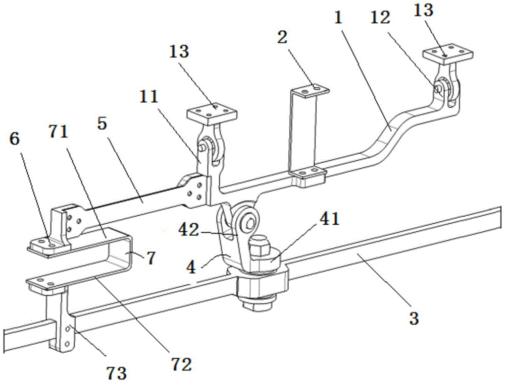
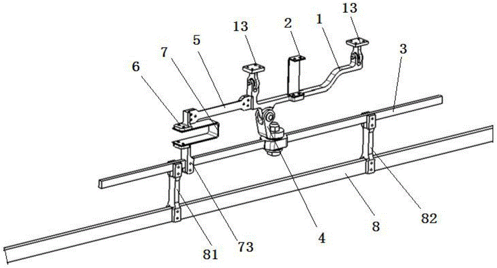
[0023] Such as figure 1 and figure 2 As shown, the aircraft missile system flutter model provided by the present invention includes a general pylon beam 1, a special pylon beam 3, a missile model 8 and a side flat spring piece 2, a rotating support arm 4, and a yaw Spring leaf 5 and pitch spring leaf 7 and other components.

[0024] The universal hanger beam 1 can adopt various suitable structures, and has protruding first fixing parts 11 and second fixing parts 12 at the top surfaces of both ends of the universal hanger beam 1 along the direction perpendicular to the axis of the universal hanger beam 1 . Wherein, one end of the first fixed part 11 and the second f...


PUM


Abstract

The invention relates to the field of aviation experiments, in particular to a flutter model of a plane missile system. The flutter model solves the problems that at present, pitch and yaw mode coupling of a flutter model is not prone to being identified, and rigidity adjustment is inconvenient. According to the flutter model of the plane missile system, rigidity of a missile model in the three directions is decoupled, and identification of a side flat mode, a yaw mode and a pitch mode in an experiment is facilitated; in addition, three replaceable leaf springs which are correspondingly arranged simulate frequencies of the side flat mode, the yaw mode and the pitch mode of a missile respectively; the leaf springs can be replaced so as to adjust the frequency of a certain mode of the missile model, the frequency adjustment on the missile model in the experiment can be facilitated, experimental expenses are saved, and the experimental time is shortened.

Description

technical field [0001] The invention relates to the field of aviation tests, in particular to a flutter model of an aircraft missile system. Background technique [0002] Various types of missiles need to be suspended at the bottom of the aircraft wing. When designing the flutter model of this type of aircraft, it is required to simulate the three modes of missile lateral level, pitch and yaw according to the requirements. In the past, the stiffness of the three directions of the missile was simulated in the form of a composite beam frame, and there were problems such as difficult identification of pitch and yaw modal coupling and inconvenient stiffness adjustment. Contents of the invention [0003] The purpose of the present invention is to provide a flutter model of an aircraft missile system to solve the problems of difficult identification of pitch and yaw modal coupling and inconvenient adjustment of stiffness in current flutter models. [0004] Technical scheme of t...

Claims


Application Information

Patent Timeline
Patent Type & Authority Patents(China)
IPC IPC(8): B64F5/00B64F5/60
Inventor 张红波马翔陈海
Owner XIAN AIRCRAFT DESIGN INST OF AVIATION IND OF CHINA
Learn More