
Glass disc cutting method

A cutting method and glass technology, which are applied in glass cutting devices, glass manufacturing equipment, manufacturing tools, etc., can solve the problems that the upper and lower drill bits are not coaxial, and the coaxial difficulties of the upper and lower drill bits are difficult.

Inactive Publication Date: 2015-11-25
黄家军
View PDF6 Cites 3 Cited by
  • Summary
  • Abstract
  • Description
  • Claims
  • Application Information

AI Technical Summary

Problems solved by technology

Although this can solve the problem of edge blasting to a certain extent, it is very difficult to keep the upper and lower drill bits coaxial
There will be an obvious drill mark on the side wall of the glass disc drilled by this method, which is caused by the different axes of the upper and lower drill bits.

Method used


Image

  • Glass disc cutting method
  • Glass disc cutting method
  • Glass disc cutting method

Examples


Embodiment Construction

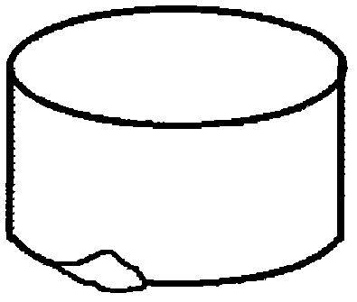
[0014] figure 1 It is a schematic diagram of a fried edge glass disc. The edge of the glass disc shattered.

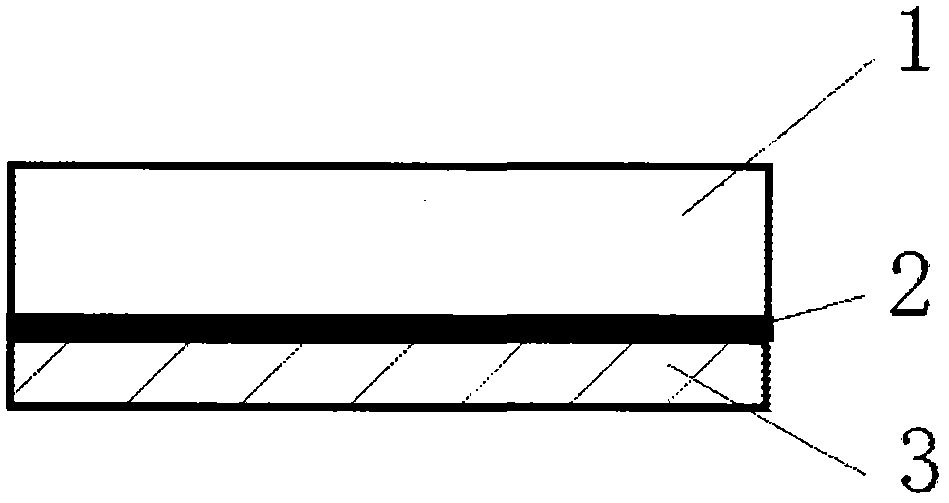
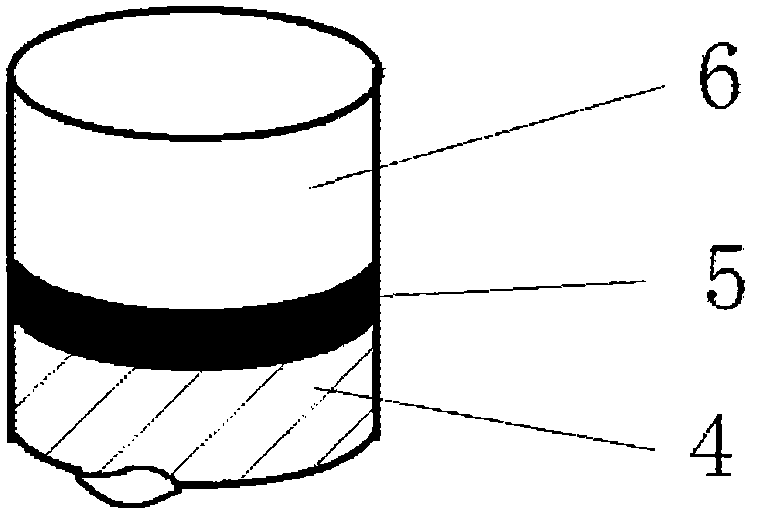
[0015] figure 2 It is a glass plate with a lower backing plate, which consists of a glass plate 1, an intermediate adhesive layer 2 and a lower backing plate 3, and what the lower backing plate 3 has used is a 3 mm thick common building glass plate. The glass plate is an ordinary building glass plate, and the glue is a good adhesive. Put the glued glass plate into the glass puncher to drill holes. The drill bit is a hollow drill bit. During the drilling process, the inner and outer sides of the hollow drill bit should be cooled with water. After drilling through the glass plate, the removed glass disc is as image 3 shown. It is composed of an upper glass disc 6, an intermediate adhesive layer 5 and a lower lining glass disc 4. The lower surface of the glass disc 6 is supported by the lining glass plate 3 and fixed by the adhesive layer 2 during the drilling an...


PUM


Abstract

The present invention provides a glass disc cutting method. The method is characterized in that flat glass is bonded to a liner of whom the strength and material is similar to those of the plat glass by an adhesive before cutting. For example, when flat glass is used as the liner, upper glass and lower glass is bonded together, so that during a process of the upper layer glass being cut by a lip of a hollow drill, when the upper glass left only about 1 mm, as the strength of the lower layer glass is the same as that of the upper layer glass, during the drill lip pushing, downward bending deformation of the glass under the drill lip is effectively limited due to the support of the lower glass, thereby avoiding crack edges.

Description

technical field [0001] The invention belongs to the field of glass processing, in particular to a method for cutting glass wafers. technical background [0002] Glass discs less than one square centimeter are cut by laser, and the cut glass discs are neat and beautiful, but the efficiency is low and the cost is high. It can also be drilled with a diamond glass drill bit, but the edge of the lower layer is easy to fry. The reason for the edge explosion is that the downward movement of the drill bit has a downward pressure. When the thickness of the glass under the drill bit is less than 1mm, it cannot withstand the pressure under the drill bit. In addition, the high-speed rotating drill bit has a dynamic impact on the glass, and Glass is a particularly brittle material, and it is difficult to avoid fried edges. The traditional solution is to install a hollow drill bit on the top and bottom respectively, and the two drill bits are drilled relative to each other. The lower dr...

Claims


Application Information

Patent Timeline
Patent Type & Authority Applications(China)
IPC IPC(8): C03B33/04
Inventor 黄家军
Owner 黄家军
Learn More