Novel fingerprint lock

A fingerprint lock, a new type of technology, applied in building locks, lock applications, electric locks, etc., can solve the problems of low reliability of unlocking, complex internal structure, short service life of electronic locks, etc., to achieve convenient control and unlocking, The effect of guaranteeing service life, guaranteeing reliability and flexibility

Inactive Publication Date: 2015-11-25
中山市皆安电子科技有限公司
View PDF5 Cites 5 Cited by
  • Summary
  • Abstract
  • Description
  • Claims
  • Application Information

AI Technical Summary

Problems solved by technology

[0002] With the continuous development of locks, various types of electronic locks have been continuously developed and manufactured, especially electronic locks designed by combinations of wireless remote control, password setting, fingerprint recognition, and emergency opening. The unlocking system makes its internal structure complex, the reliability of unlocking is low, and the service life of electronic locks is short

Method used


Image

  • Novel fingerprint lock
  • Novel fingerprint lock
  • Novel fingerprint lock

Examples


Embodiment 1

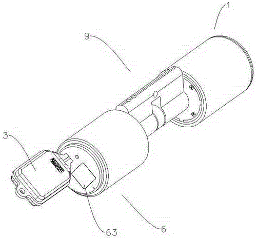
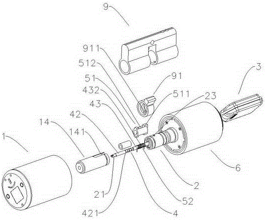
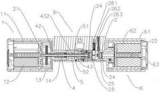
[0037] refer to Figure 1 to Figure 7 , Figure 1 to Figure 7 It is a structural schematic diagram of the first specific embodiment of the present invention. As shown in the figure, a novel fingerprint lock includes: a lock body 9, an inner handle 1, an outer lock head 2, an outer handle 6, and a clutch device.

[0038] As shown in the figure, the middle part of the lock main body 9 is provided with an unlocking driving device. In this embodiment, the unlocking driving device is an unlocking dial 91 , and the matching lockset is unlocked by turning the bolt through the unlocking dial 91 .

[0039]As shown in the figure, the inner handle 1 is arranged at one end of the lock main body 9, which includes a handle shell 11, a battery pack 12, a motor 13 and a motor control circuit arranged in the handle shell 11, and the inner handle 1 passes through A connection lock sleeve 14 is connected to the unlocking drive device, and the motor 13 is a double drive motor, which includes two...

Embodiment 2

[0055] refer to Figure 8 to Figure 10 , Figure 8 to Figure 10 It is a structural schematic diagram of the second specific embodiment of the present invention. As shown in the figure, in this embodiment, the lock is a double unlocking tool, the sliding part is a square part 53, and the unlocking driving device is a set with a The rotation unlocking mechanism of the square hole that square piece 53 cooperates, in this implementation, except spring guide clutch device 5 and unlocking driving device, other structures are similar to the first specific embodiment, and because in the present embodiment, lockset is a double opening The lockset is provided with a corresponding fingerprint identification device 63 and an electronic key 3 on the inner handle 1, and the principle of its structure will not be described in detail here.

[0056] As shown in the figure, the square piece 53 is formed by combining two 7-shaped hardware pieces 53a, 53b. The two hardware pieces 53a, 53b can sl...

Embodiment 3

[0059] refer to Figure 11 to Figure 13 , Figure 11 to Figure 13 It is a structural diagram of the third specific embodiment of the present invention. As shown in the figure, in this embodiment, the lock is an escape-type lock whose interior is always in an unlockable state, and the connecting lock sleeve 14 is provided with a square piece 54 , the unlocking driving device is a rotating unlocking mechanism provided with a square hole matched with the square piece 54, so that the outer handle 6 can be rotated to directly open the lock, which is convenient for escape; in this embodiment, the buffer device 4 is simplified, except Except that the spring guide clutch device 5 and the inner handle 1 are not provided with an unlocking device, other structures are similar to the second embodiment, and the principle of its structure is not described in detail here.

[0060] As shown in the figure, the output end of the motor 13 is provided with a tube shaft 42 set on the hollow condu...


PUM


Abstract

The invention discloses a novel fingerprint lock. The novel fingerprint lock comprises a lock body, an inner grab handle, an outer lock head, an outer grab handle and a clutch device. The clutch device comprises a spring guide clutch device body. The outer grab handle is provided with a fingerprint recognition device. When the fingerprint recognition device is matched successfully, a motor drives a connecting tube shaft to rotate. A sliding piece can be driven to move forwards or backwards through the rotating fit between a convex lug and the threaded structure of a spring, and thus the clutch function is achieved. The elastic compression performance of the spring is further utilized, pushing force is increased gradually, and engaging and disengaging reliability and flexibility of the clutch device are guaranteed. Besides, in the actual use process, when the convex lug is rotated to the tail end of the spring, a spring wire of the spring can be slid out; idling operation of the motor can be achieved without stopping, overlarge loads of the motor are avoided and the service life of the motor is guaranteed. When the motor is rotated reversely, the convex lug can slip into the threaded spring wire automatically, and both controlling and unlocking are convenient and reliable.

Description

technical field [0001] The invention relates to a novel fingerprint lock. Background technique [0002] With the continuous development of locks, various types of electronic locks have been continuously developed and manufactured, especially electronic locks designed by combinations of wireless remote control, password setting, fingerprint recognition, and emergency opening. The unlocking system makes its internal structure complex, the reliability of unlocking is low, and the service life of the electronic lock is short. Contents of the invention [0003] In order to overcome the deficiencies of the prior art, the invention provides a novel fingerprint lock. [0004] The technical solution adopted by the present invention to solve its technical problems is: [0005] A new type of fingerprint lock, including: [0006] The lock main body, an unlocking driving device is arranged in the middle of the lock main body; [0007] Inner handle, the inner handle is arranged at o...

Claims


Application Information

Patent Timeline
Patent Type & Authority Applications(China)
IPC IPC(8): E05B47/00E05B49/00G07C9/00
Inventor 刘建刚
Owner 中山市皆安电子科技有限公司
Why Eureka
Try Eureka