
Self-supporting internal combustion engine gas fuel supply system and gas bag pressure control method

A gas fuel and supply system technology, applied in the direction of fuel injection control, charging system, electrical control, etc., can solve the problems of large mutual influence of the system, unfavorable long-term safety of the system, efficient operation, low level of automation, etc., and achieves vacuum fluctuations. small effect

Active Publication Date: 2017-06-20
JIANGSU UNIV OF SCI & TECH
View PDF5 Cites 1 Cited by
  • Summary
  • Abstract
  • Description
  • Claims
  • Application Information

AI Technical Summary

Problems solved by technology

However, the classic control is greatly affected by the performance of discrete devices, and the subsystems in the system have a great influence on each other. The automation level is not high, the control effect is not very ideal, and it is prone to failure, which is not conducive to the long-term safe and efficient operation of the system.
Modern control is suitable for control objects with linear and precise mathematical models, but it is too difficult to establish precise mathematical models for control systems such as air bag pressure, so it is not an ideal choice

Method used


Image

  • Self-supporting internal combustion engine gas fuel supply system and gas bag pressure control method
  • Self-supporting internal combustion engine gas fuel supply system and gas bag pressure control method
  • Self-supporting internal combustion engine gas fuel supply system and gas bag pressure control method

Examples


Embodiment Construction

[0034] Below in conjunction with embodiment the present invention will be further described.

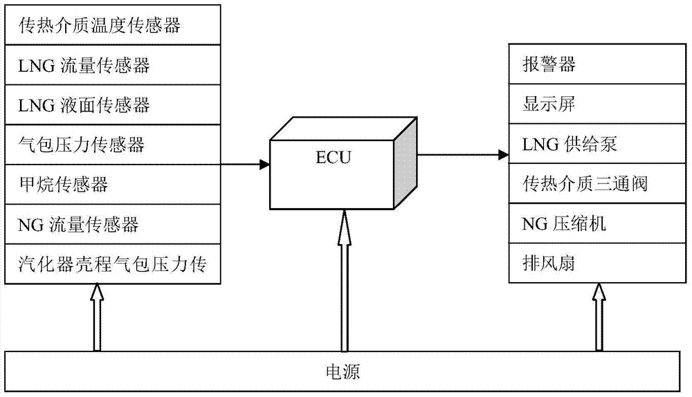
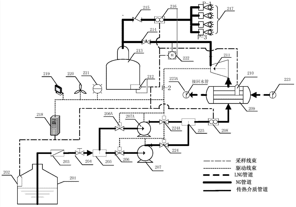
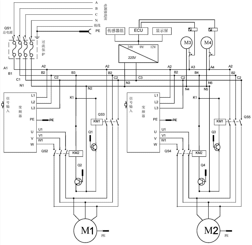
[0035] Such as Figure 1 to Figure 6 As shown, a self-contained internal combustion engine gas fuel supply system includes LNG tank 201, LNG supply pump 207, LNG vaporizer 209, NG compressor 211, gas bag 213 and NG injection valve 217, between the LNG tank and the LNG vaporizer The LNG delivery section is connected in turn with LNG filter 203, manual valve 204, front three-way 205, front solenoid valve 206, LNG supply pump 207, rear solenoid valve 224, rear three-way 225 and LNG flow sensor 208, front three-way 205 Two pipelines are used between the rear three-way 225, the front three-way one is connected to the front solenoid valve 206, the LNG supply pump 207, the rear solenoid valve 224 and one interface of the rear three-way 225, and the other front three-way is connected to the spare pipeline The front solenoid valve 206A, the backup pipeline LNG supply pump 207A, the backup pi...


PUM


Abstract

The invention discloses a self-sufficient internal combustion engine gas fuel supply system and a gas bag pressure control method. The system includes an LNG tank, an LNG supply pump, an LNG vaporizer, a gas bag and an NG injection valve; during operation, the liquefied natural gas stored in the LNG tank is Under the action of the LNG supply pump, it flows to the shell side of the LNG vaporizer, where it absorbs heat and turns into gaseous natural gas, which is stored in the gas bag. The NG injection valve injects a certain amount of gaseous fuel into the inlet, and circulates through the heat transfer medium in the high-temperature section of the cooling system. The heat transfer medium flows into the LNG carburetor tube through the three-way valve. After releasing heat, it flows back to the low-temperature section of the cooling system and flows back into the cylinder liner of the internal combustion engine to absorb heat. This cycle continues. The method of the present invention comprehensively adopts fuzzy controller, Smith predictor and artificial immune controller, and can dynamically optimize the LNG supply flow and heat transfer medium flow according to changes in gas bag pressure and NG flow, so as to stabilize the gas bag pressure. In a given region, the nonlinearity of the system and the influence of time delay are well overcome.

Description

technical field [0001] The invention relates to a gas fuel supply system for a self-supporting internal combustion engine and a gas bag pressure control method, belonging to the field of internal combustion engines. Background technique [0002] Compared with traditional petroleum fuels, liquefied natural gas (LNG) has the characteristics of low carbon, high efficiency, high quality and cleanness, and is an ideal alternative fuel for internal combustion engines. Since LNG is stored and transported at a low temperature of -163°C under normal pressure, it is pre-evaporated into gaseous fuel (NG) before it can be burned for work in practical applications. However, compared with gas stations in the current market, gas stations are far less perfect in terms of quantity and regional distribution, which greatly limits the use of LNG on long-distance vehicles (ships, intercity buses and trucks). . In order to break through the shortcomings of few and uneven distribution of gas fil...

Claims


Application Information

Patent Timeline
Patent Type & Authority Patents(China)
IPC IPC(8): F02M21/02F02M21/06F02D41/00F02D41/22
CPCY02T10/30
Inventor 袁春元潘秀杰周宏根王新彦蔡羽凡
Owner JIANGSU UNIV OF SCI & TECH
Learn More