
A concrete vacuum suction device

A vacuum water absorption and concrete technology, which is applied in the direction of ceramic molding mandrel, ceramic molding machine, manufacturing tools, etc., can solve the problems of shortening the service life of the vacuum machine, damage of the vacuum machine, and large fluctuation of vacuum degree, so as to reduce production costs and absorb water. The effect of shortening the time and reducing the fluctuation of the vacuum degree

Active Publication Date: 2019-10-01
韩文强
View PDF15 Cites 0 Cited by
  • Summary
  • Abstract
  • Description
  • Claims
  • Application Information

AI Technical Summary

Problems solved by technology

[0009] The patents disclosed above are all vacuum machines directly connected to the mold through pipes, and a filter cloth is installed inside the mold. The filter cloth is mostly made of glass fiber cloth or non-woven fabric, and the filter cloth can prevent sewage, sundries, cement thinner, etc. from entering The vacuum machine can effectively protect the vacuum machine, but some dirt will always enter the vacuum machine, causing damage to the vacuum machine and shortening the service life of the vacuum machine
Furthermore, since the filter cloth is relatively soft, the laying process of the filter cloth is cumbersome, and it is not easy to lay and fix, and the filter cloth is easy to stick to the cement slurry, and it has to be replaced after several uses, which greatly increases the production cost.
If the area of ​​the prefabricated part is too large, the vacuum machine will work all the time, and it is difficult to control the vacuum degree. If the vacuum degree is too small, the water cannot be sucked out. suction

Method used


Image

  • A concrete vacuum suction device
  • A concrete vacuum suction device
  • A concrete vacuum suction device

Examples


Embodiment 1

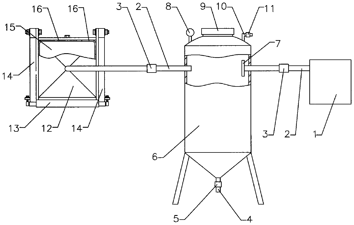
[0046] Example 1: as attached figure 1 As shown, a concrete vacuum suction device includes a vacuum tank 6, a plurality of connecting pipes 2 are arranged on the vacuum tank 6, at least one connecting pipe 2 is connected with a vacuum machine 1, and / or in the vacuum tank 6 on the connecting pipe 2 A filter device is provided, through which sewage, sundries, cement thin materials, etc. are effectively prevented from entering the vacuum machine 1, and the vacuum machine 1 is effectively protected.

[0047] In this embodiment, only a schematic structural diagram of the connection between one connecting pipe 2 and the vacuum machine 1 is shown, and a plurality of connecting pipes 2 can be connected between the vacuum tank 6 and the vacuum machine 1 as required.

[0048] The filter device is a filter screen 7, a filter cloth or a filter cotton. In this embodiment, a filter screen 7 is used, which can be replaced with a filter cloth or filter cotton as required, or a filter plate, w...

Embodiment 2

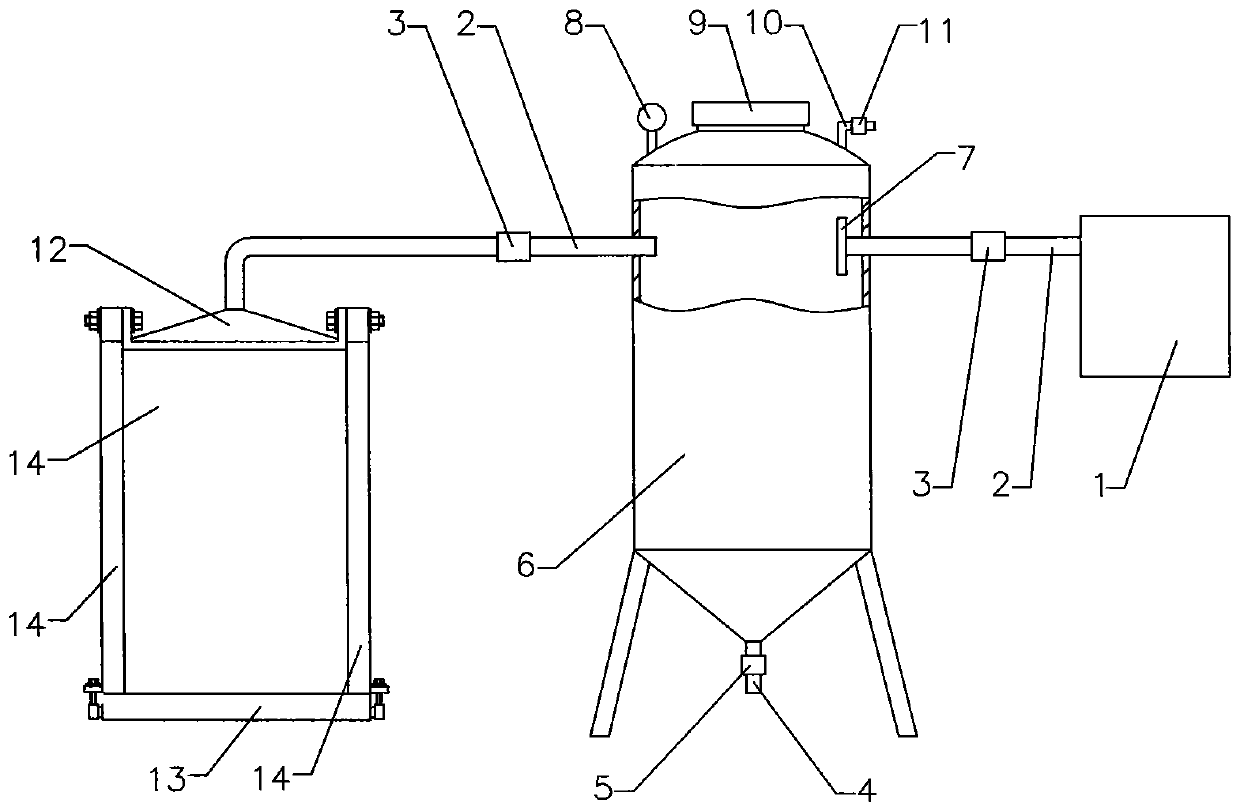
[0069] Example 2: as attached figure 2 As shown, the mold connected to the vacuum tank 6 is a vertical mold.

[0070] The other structures are the same as in Example 1.

Embodiment 3

[0071] Example 3: as attached figure 1 As shown, a concrete vacuum suction device includes a vacuum tank 6, a plurality of connecting pipes 2 are arranged on the vacuum tank 6, at least one connecting pipe 2 is connected with a vacuum machine 1, and / or in the vacuum tank 6 on the connecting pipe 2 A filter device is provided, through which sewage, sundries, cement thin materials, etc. are effectively prevented from entering the vacuum machine 1, and the vacuum machine 1 is effectively protected.

[0072] In this embodiment, only a schematic structural diagram of the connection between one connecting pipe 2 and the vacuum machine 1 is shown, and a plurality of connecting pipes 2 can be connected between the vacuum tank 6 and the vacuum machine 1 as required.

[0073] The filter device is a filter screen 7, a filter cloth or a filter cotton. In this embodiment, a filter screen 7 is used, which can be replaced with a filter cloth or filter cotton as required, or a filter plate, w...


PUM


Abstract

The invention relates to a concrete vacuum water absorption device which comprises a vacuum tank. The vacuum tank is provided with multiple connection pipes, and at least one connection pipe is connected with a vacuum machine. When the device is used, the device is connected with a die through the connection pipes, and filter cloth does not need to be arranged in the die; by means of the arrangement of the vacuum tank, vacuum storage amount is increased, the technical problems that if the vacuum machine works for a long time, the vacuum degree greatly fluctuates and water absorbing is accelerated are solved, water absorbing time is shortened, production efficiency is improved, production cost is lowered, and sewage, impurities, cement thinner and the like are sucked into the vacuum tank through the connection pipes; filtering is achieved through a filtering device, the sewage, the impurities, the cement thinner and the like can not enter the vacuum machine, and the vacuum machine can not be damaged.

Description

technical field [0001] The invention relates to a vacuum water absorption device, in particular to a concrete vacuum water absorption device. Background technique [0002] Exhaust duct is a duct product used to eliminate the flue gas generated by kitchen cooking activities or the turbid air in the bathroom. It is also called exhaust duct, ventilation duct, and residential exhaust duct. Residential exhaust duct is a shared exhaust duct system for residential kitchens and bathrooms. main components. [0003] In order to improve the production efficiency of exhaust pipes, air cap tops and other prefabricated cement components, most of the exhaust pipes, air cap tops and other prefabricated cement components are produced by molds. After injection into the mold, through vibration and tamping, the slurry contains a lot of water, and it takes a long time to cure before demoulding, which reduces the production efficiency. [0004] In order to improve the production efficiency of t...

Claims


Application Information

Patent Timeline
Patent Type & Authority Patents(China)
IPC IPC(8): B28B7/22B28B7/28B28B17/00B28B1/08
Inventor 李晓巧韩文强
Owner 韩文强
Learn More